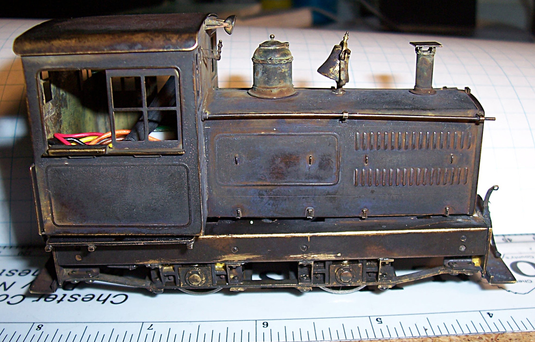
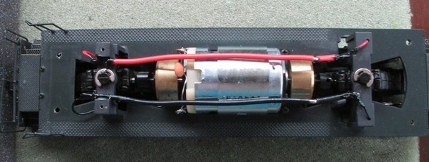
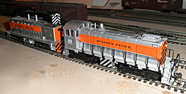
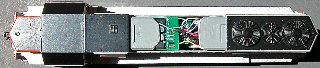
This is a large HO scale brass loco; a 4-8-4 with a humongous tender. The objective is full S-CAB installation; both radio control and battery power. It's obvious, everything will fit into the tender, but the loco is an oil burner and the tender is all brass. Since there is no radio reception inside a closed brass box (the tender), the antenna must be mounted externally, but there's no coal load, which is my favorite antenna hiding place. Other concerns are the model's age and its solder joints, which have weakened over time, and avoiding damage to paint-work, which was/is still in pretty good condition.
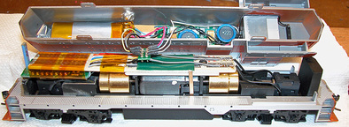
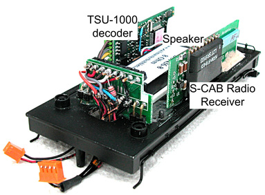
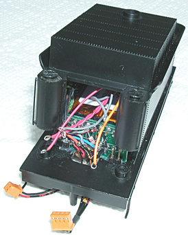
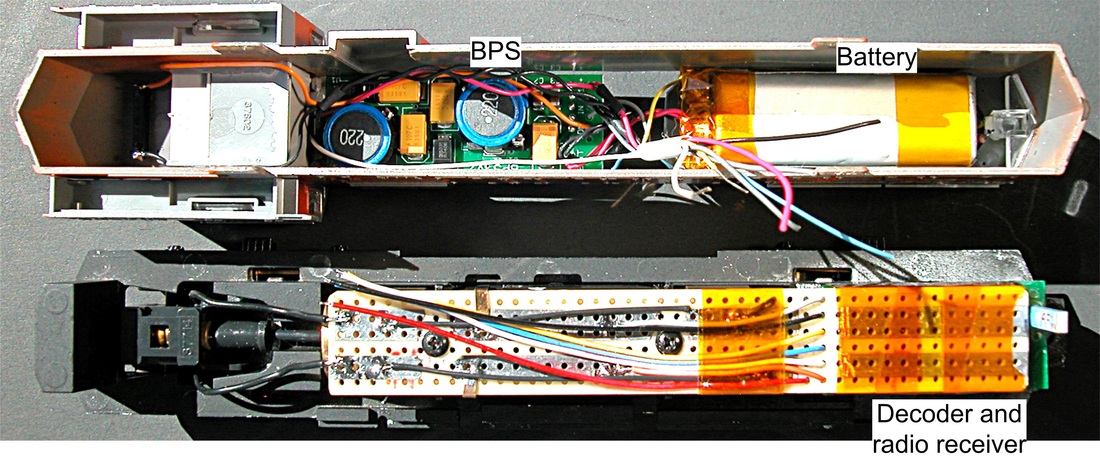
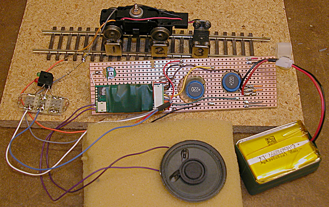
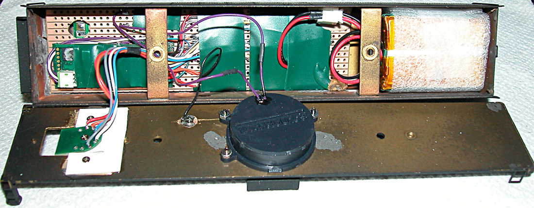
Since loco owner Bill had already decided to replace loco motor and gearbox drive shaft, we agreed to split the project; he would work on engine renovation and I would install electronics and battery in the tender. We just needed to agree on wire connections between tender and engine, and this, I have described in a previous blog. What follows here is the rest of the tender installation, as illustrated in the following photograph.
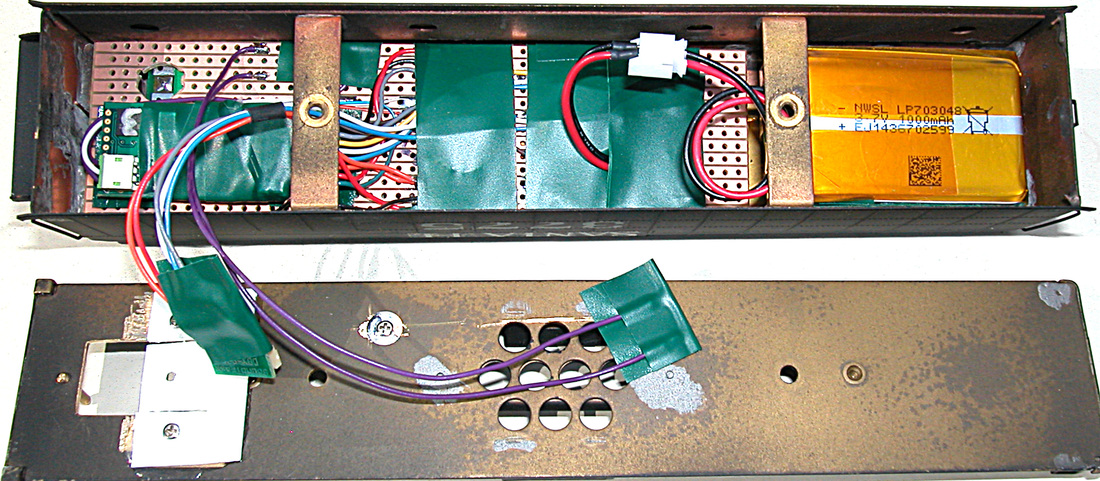
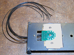
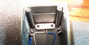
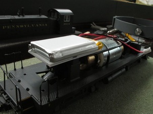
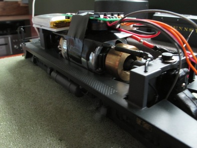
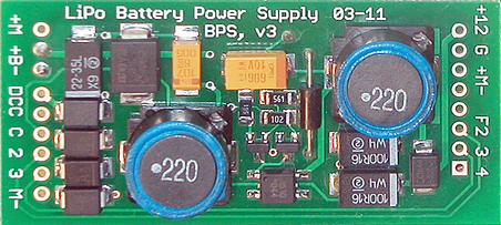
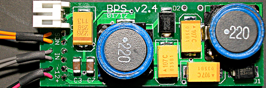
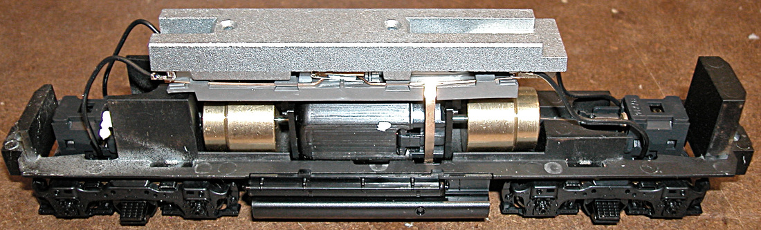
All electronic components are mounted on a piece of electronic prototyping board and the whole assembly fits flush against the top of the tender. The radio receiver and BPS circuit board are out of sight behind the mounting board and the decoder is visible to the left side in this view. The tender is wide enough to accommodate 1000 mAh LiPo cells and deep enough to use a triple-pack (3 cells in parallel) giving 3 AH (amp-hours) storage capacity. Connections to the loco and speaker were temporarily insulated with green electrical tape while photographing.
The Antenna
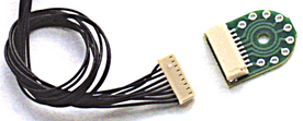
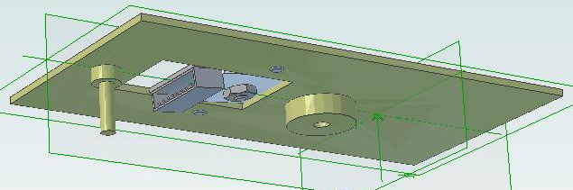
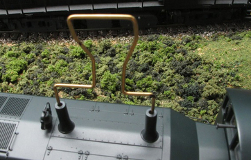
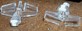
I considered two possibilities for the antenna; a length wire (approx. 3") disguised as a handrail, or a very small antenna from Linx Technologies (https://www.linxtechnologies.com/resources/data-guides/ant-916-jjb-xx.pdf)
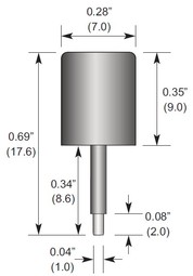 Linx Technologies JJB antenna |  Mounting the JJB required a small hole and significantly less work than adding a handrail. However, keeping the hole small and hiding any chipping of paint required the antenna to be inserted from outside the tender and soldered to the radio receiver from inside. In other words, all components, except the antenna, are mounted on the prototyping board before installation. After final installation, the antenna must be unsoldered before the electronic assembly can be removed from the tender. This is an unlikely event and not as difficult as it appears. |
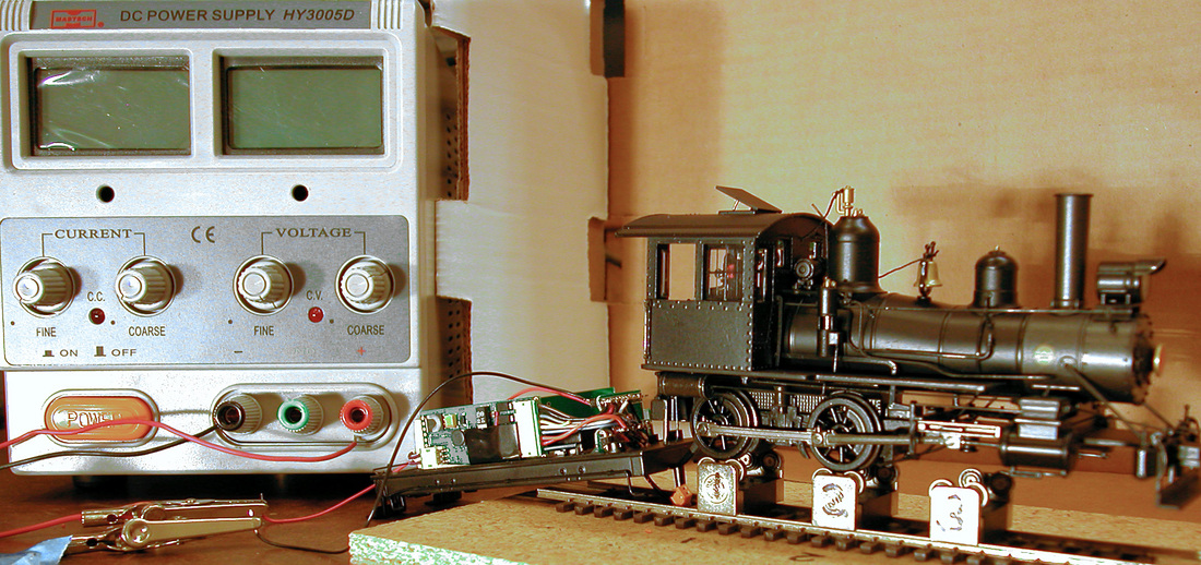
Testing
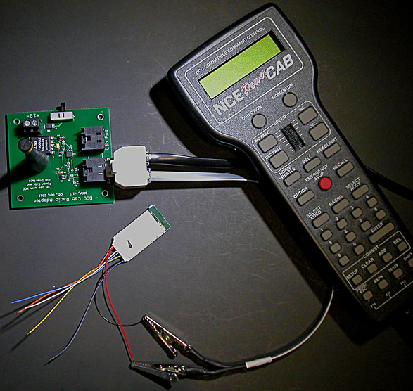
One version of Murphy's Law says "if its not tested, it won't work" and its a lot easier to test and fix problems on the workbench. Since I had not previously used the JJB antenna, I was concerned about its performance and tested its range using an S-CAB throttle. Results were excellent. However, the critical test was performance with components in the tender and for this test I did a trail installation. Results were good.
Battery
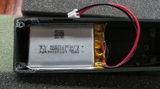
With Bill installing a new motor, I don't know its power consumption, but I'm quite confident 3 amp-hours battery storage will keep the loco running long enough to test the stamina of the most enthusiastic operators. The battery fits neatly in the available space and is easily removed.
Final Assembly
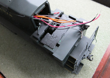
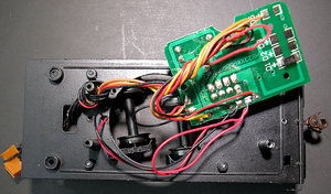
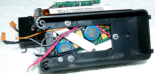
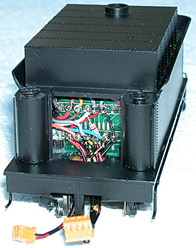
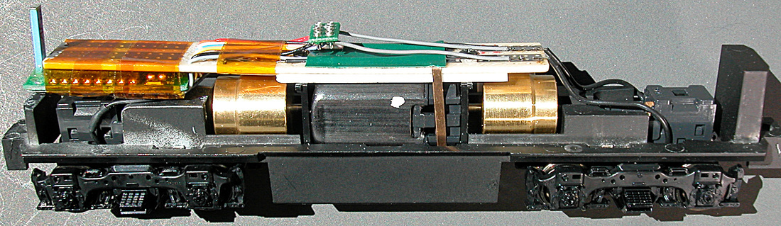
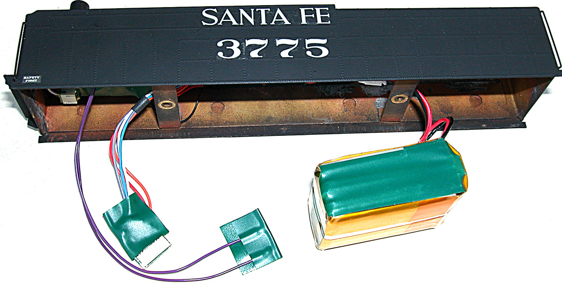
Wiring complete and ready to close the tender
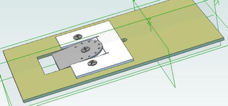
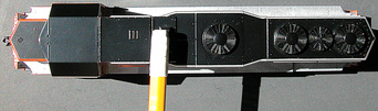
The antenna sits flush on top of the tender, held in place by the soldered connection to the radio receiver. Since brass is non-magnetic, it does not interfere with operation of the BPS magnet sensor positioned against the tender's top where it's conveniently operated with a magnetic wand used to turn on battery power. The component mounting board is fixed in place by a couple of dabs of hot glue; just enough to prevent movement. The battery is wrapped in foam plastic to prevent it rattling around once the tender body is mounted on the chassis.
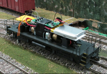
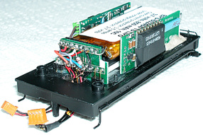
Ready to Run
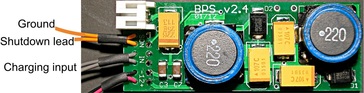
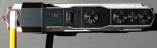
The installation is wired to charge the battery from track power, if available. As is common practice with brass locos, right rail pickup is from the loco and un-insulated tender wheels provide the left rail connection. The battery power supply turns on automatically when track power is detected. When no track power is present, a magnetic wand waved slowly across the tender top above the Santa Fe name turns on battery power. The Tsunami T-1000 decoder, function F5, is used to turn off the battery at the end of an operating session. Decoder address is "5".
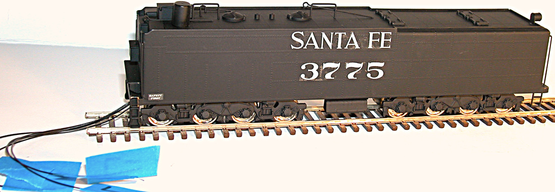
Conversion complete and tender ready to roll. Five wires (motor+/-, headlight+/- and right rail pickup) connect to the loco.