The availability of new and upgraded components has initiated a major update of the website. New versions of Home, Radio Control and Battery Power pages are already online and others will be published as editing progresses. Here are a few areas with significant new information.
S-CAB Upgrades
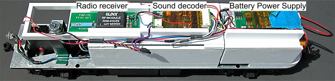
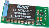
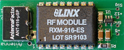
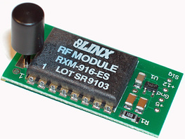
New versions of S-CAB radio receiver (LXR) and Battery Power Supply (BPS) are available
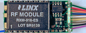
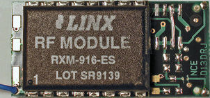
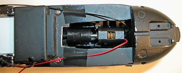
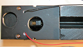
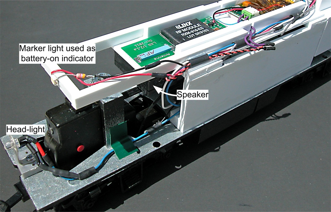
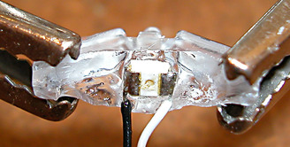
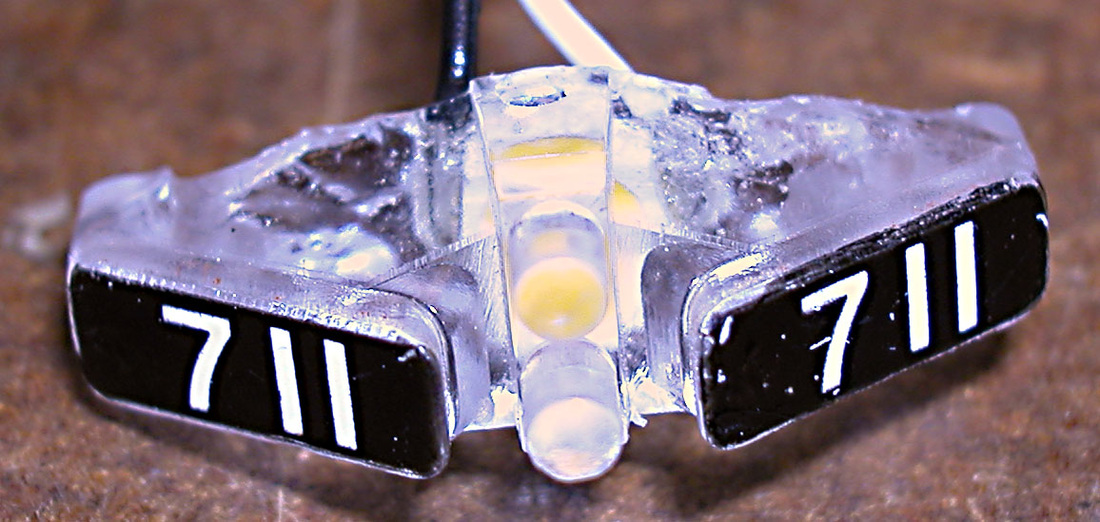
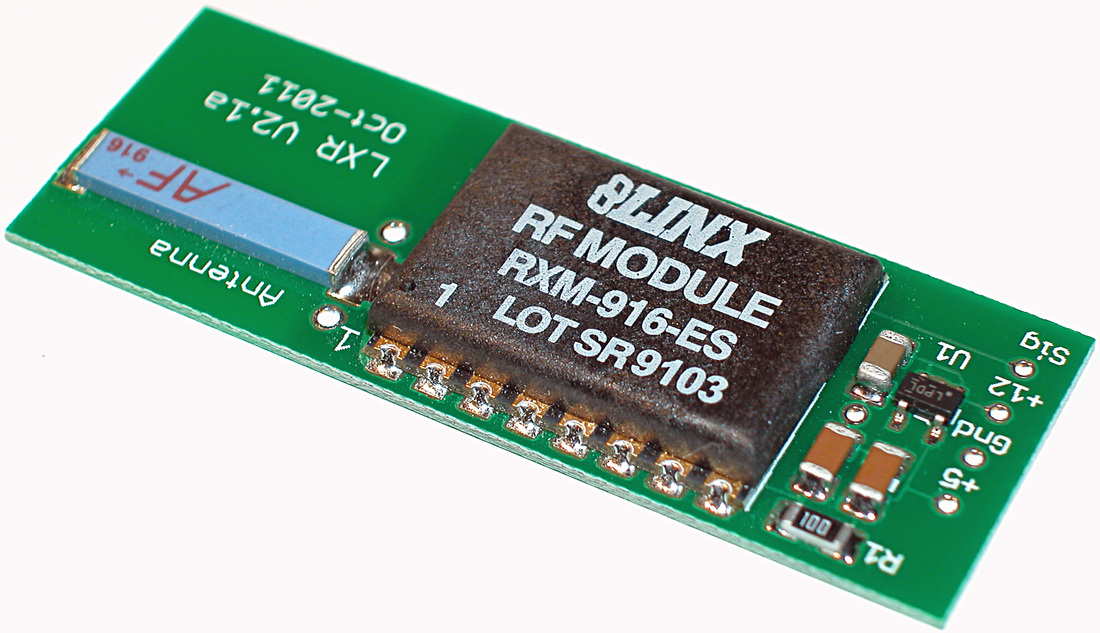
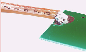
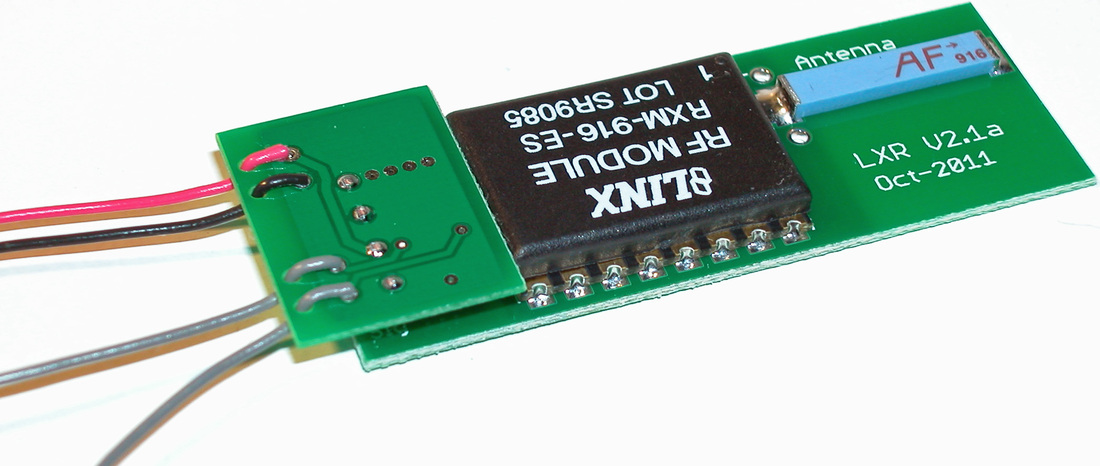
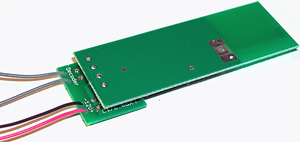
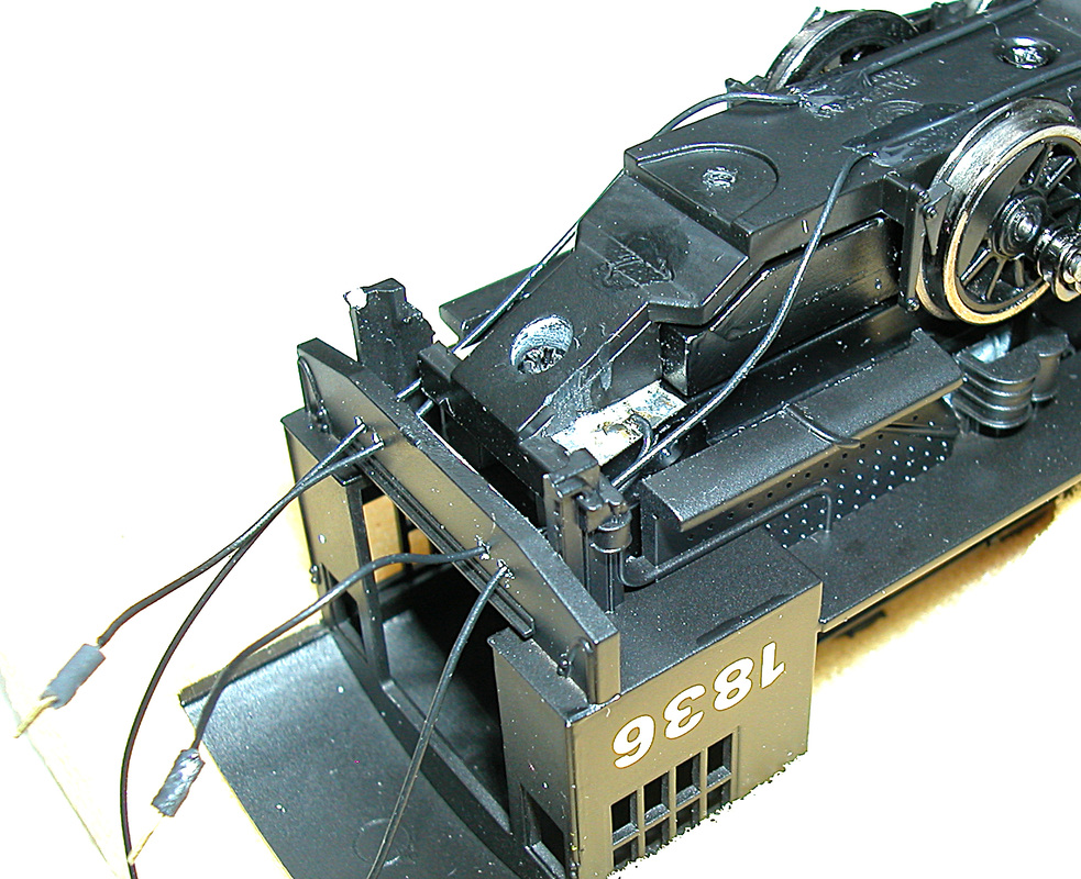
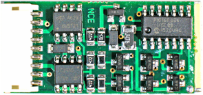
LXR: The new receiver board is designed for convenient integration with new decoders. Another design change involves antenna placement. After several years experience with various antenna orientations, the new LXR standardizes cross-wise mounting as shown in the photo. Vertical mounting is still available by special order, but horizontal (lengthwise) is discontinued, since it offers no performance advantage and increases overall length of the receiver.
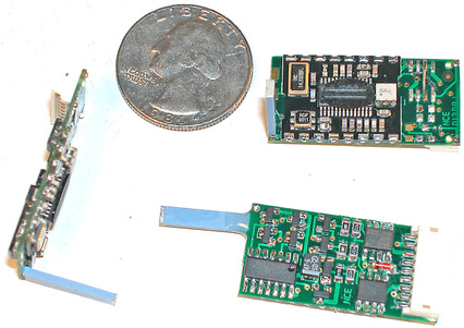
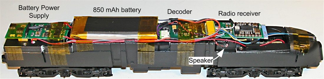
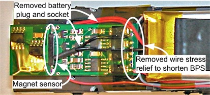
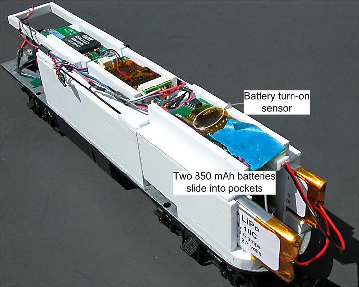
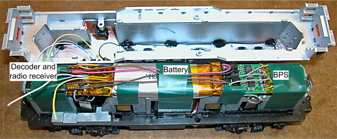
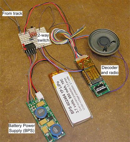
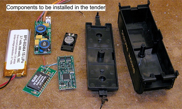
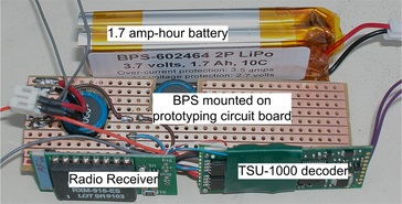
BPS: A complete redesign of the Battery Power Supply provides major improvements:
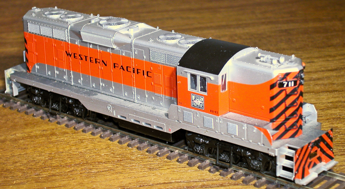
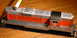
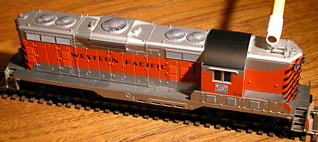
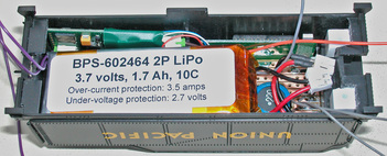
- Size reduction: It's not dramatic, but decreased width is very helpful in narrow hooded diesels (GPs).
- Maximum output is increased from 500 to 750 mA.
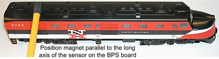
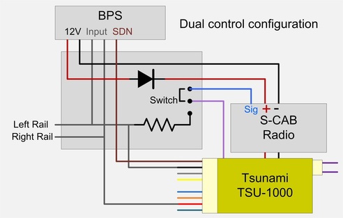
- Integrated battery bypass operates loco from track power when available, and provides automatic, instantaneous battery backup. Deadrail operation or isolated battery power is optional.
- Battery under-voltage protection has been improved.
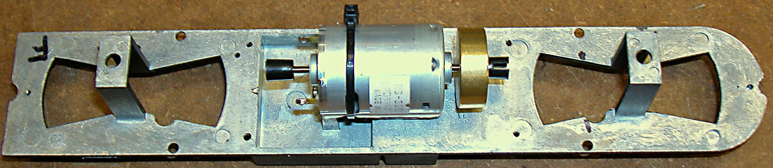
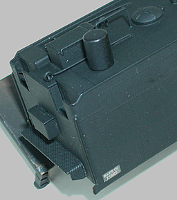
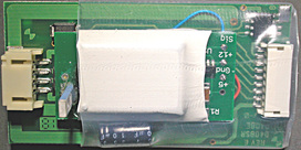
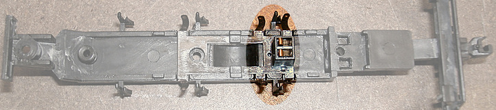
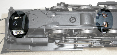
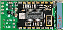
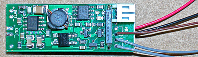 Battery switch and charger side | 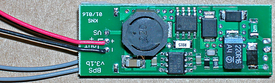 Step-up converter side |
New Decoders
New decoders, which simplify S-CAB installation, have been selected as standard products for S-CAB systems.
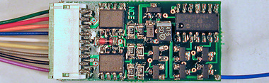
- NCE D13DRJ: Combines a non-sound decoder with S-CAB compatible receiver on the same circuit board.
- SoundTraxx ECO-100: A 1 amp, 4 function sound decoder in a very small package that integrates nicely with S-CAB receiver
 NCE D13DRJ decoder | 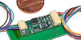 ECO-100 sound decoder |
Decoders referenced in this blog are manufactured by NCE Corporation and SoundTraxx respectively.
Product names, trademarks, copyrights and other proprietary rights of these companies are acknowledged.
Product names, trademarks, copyrights and other proprietary rights of these companies are acknowledged.