Radio Control and Battery Power for Model Railroads
  • Home
  • Radio Control
  • Battery Power
    • Batteries Explained
    • Battery Care
  • Quick Start
    • Getting Started
  • Price List
  • Documents
    • Hints, Comments, Notes
  • Contact Us
  • Neil's Blog

Atlas-Kato GP-7 Installation

8/4/2016

 
Picture
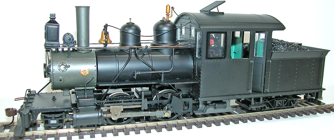
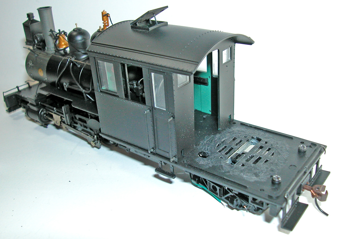
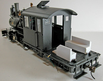
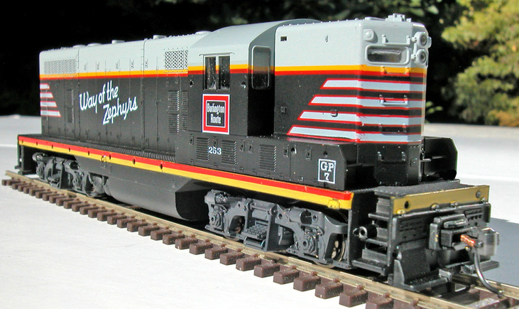
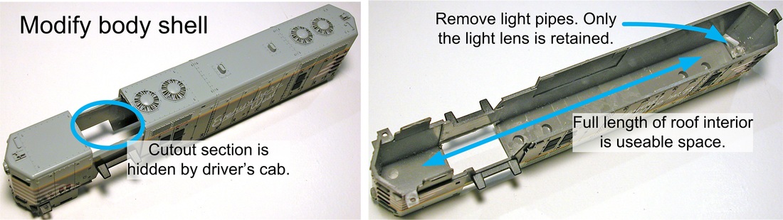
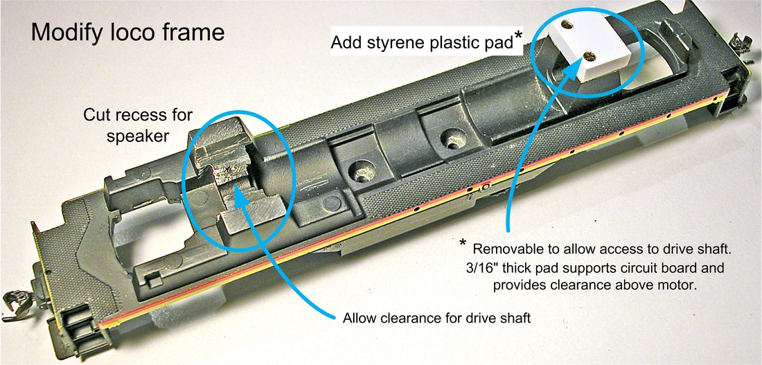
​Introduced 1987-89, these models, which were manufactured by Kato and sold by Atlas, have excellent mechanisms and are great candidates for S-CAB battery power and radio control. The cast metal frame is heavy enough for traction, but leaves space above the motor for electronics and battery. With some careful trimming of the body shell, this space can be extended the full length of the loco. The completed installation (photo left) shows no evidence of any modification to the loco.
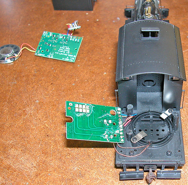
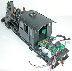
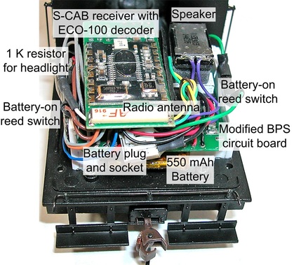
​This description illustrates use of a circuit board (sometimes called a "motherboard") to simplify installation and complete as much work and testing as possible on the workbench. Wiring within the loco is minimized by mounting front and rear lights on the components circuit board. As a result, there are no wires connected to the body shell, which can be removed and replaced without restriction. The project involves modification of the loco body and frame, assembly and test of two subsystems and finally, installation.

Loco Modifications

Picture
Picture

Subsystems

Picture

Picture

Picture

Assembly

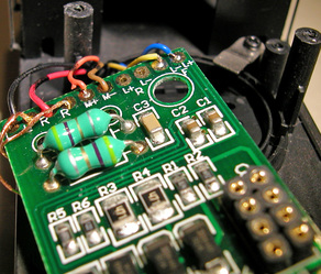
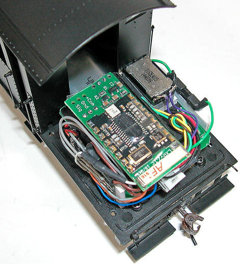
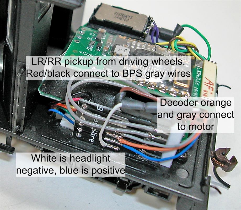
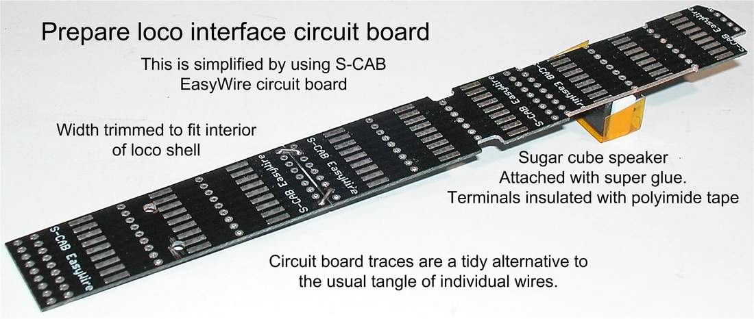
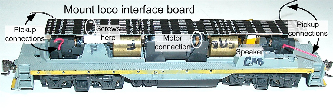
​Traces on the loco interface circuit board are used for rail pickup connections to front and rear trucks. If convenient, motor connections can also be to this board, which makes a total of 6 wires (2 to each truck and 2 to the motor) to be disconnected should it ever be necessary to remove motor or trucks. 
Picture
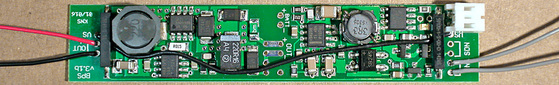
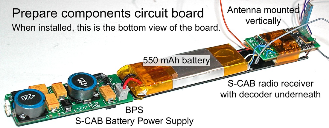
​The component board sits on top of the interface board and is held in place by electrical tape.
Picture
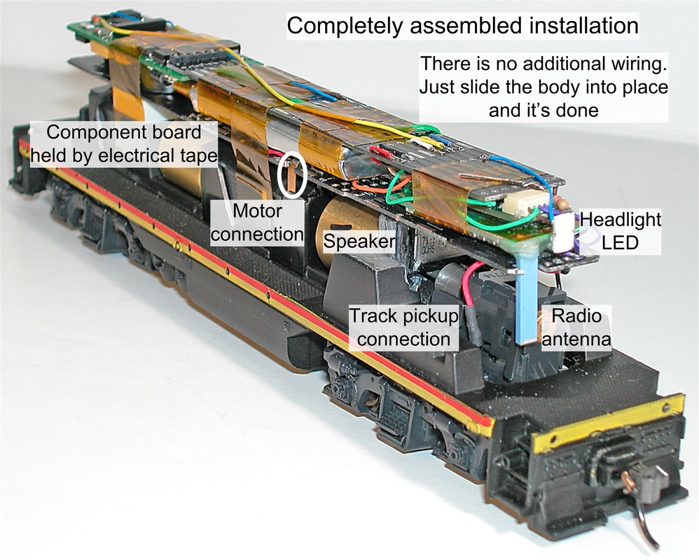
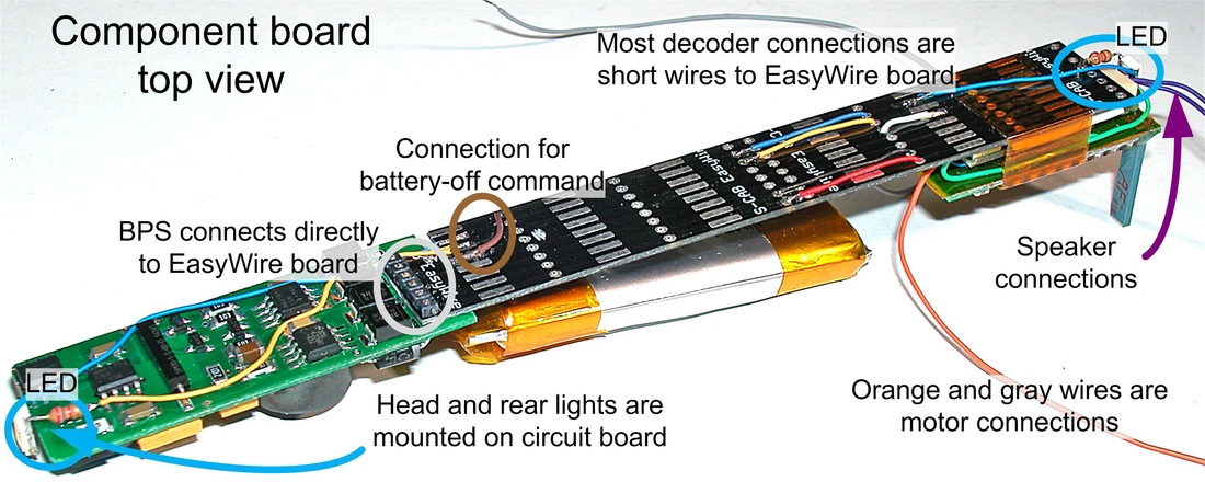
Since LED lights are mounted on the components board, there are no connections to the loco body, which simply slips into place to complete the installation.

On3 Climax Battery Power Installation

8/4/2016

 
I occasionally hear from an S-CAB user (Michael) who models On3. Since he's an innovative guy, as well as a skilled modeler, his feedback is always interesting. His latest effort is an S-CAB radio and BPS battery power supply installation for a Climax loco.
Picture
Picture
Here are Michael's comments:
​
Thought you would like to see my latest car (trailing) for the battery and BPS electronics board. The decoder/wireless/speaker are in the Climax but I need a car for the battery etc.

You will note the two pipes (lower left with the chain over the pipes) – these are for power to the loco – there are two small plugs on the loco on the same side, so thin wires will do the connection.

Also, on the top rear of the tank are two small pipes – one higher than the other – these are the recharge points.  Just plug in the power supply and the recharge will start.  The tank is not firmly secured on the flat car just sort of held in position with the chains.  The barrels etc are glued down.  The chain (not glued) at the back is part of the chain keeping the tank in position.

I have two magnetic reed switches (the ones you supplied) glued up at the top inside both ends of the tank. So I just wipe with the magnetic wand for start and stop. 

In the background is another battery car – the tank.

Full S-CAB Installation in On30 Forney

8/3/2016


Project

This is a complete battery power, radio control, sound installation in a Bachmann On30 Forney. The entire system fits under the coal load with the battery barely visible where it protrudes on the floor of the driver's cab.
Picture

Preparation

Since this model already has a factory-installed non-sound decoder, the hope is that installation can be simplified by use of existing wiring to motor, headlight and driver wheel rail pick-ups. It's also convenient that the fuel bunker is a separate molding attached to the frame by 4 screws.
Picture
Lifting the lid, we find a relatively large circuit board with a standard 8-pin decoder socket, decoder and speaker. None of this is reusable, but the expected 6 wires are nicely accessible, despite non-standard color coding, which fortunately is labeled on the circuit board.
Picture
Begin by clearing the clutter and planning efficient use of available space. Laying the battery flat on the loco frame and using space in the cab accommodates a 500 mAh battery. Obviously, the speaker must be mounted elsewhere. Internal space within the fuel bunker is 40 mm long, 40 mm wide and 22 mm high. Since the battery is approx. 6 mm thick, the challenge is to fit a sound decoder, S-CAB radio receiver, BPS battery power supply and speaker in the remaining 16 mm above the battery. Several arrangements are possible, but I eventually decided on a major rework of the BPS circuit board to make it a "middle layer", with radio receiver and speaker mounted at the top of the assembly. This gives good speaker acoustics and keeps the radio antenna clear of metal surfaces and wire tangles.
Picture

Modified BPS board

BPS has 2 standard arrangements. The long configuration can be cut in half and the 2 halves mounted back to back to form a short configuration.
Picture
BPS-L
This is the standard, one-sided BPS circuit board 

Because the Forney space is square, 2 halves of the BPS board are arranged side-by-side, wired with a few extra connections, and glued with epoxy, which was never considered in the original design. I remember something about "necessity being the mother of invention". It's not something I expect a user or even an experienced installer to attempt, but having done it for this project, it could be a special-order item.
Picture

Installation

​At this point we have an installation plan and a modified BPS circuit board. Let's determine if everything fits.
​First, add (using super glue) a styrene plastic frame to hold battery (the slot at bottom) and modified BPS board above between the side tabs.
The trail fit looks good, but there's still a third layer of components and some awkward wiring to fit into the remaining space.
Picture
Picture
​Here's a closeup photo of the completed installation.
And yes,  .    .    .
   .    .    .      the lid fits.
​The battery is visible though the open cab door, but there is no externally visible change to the model. 
Picture
Picture

Wiring

What to do with a tangle of wires is often considered too late in an installation. For this model, the entire installation must fit a space measuring 1.575" square (40 mm) and 0.79" high (20 mm). The planning process included component placement as well as arranging wires to minimize both quantity and length while still being able to make the required connections. The final arrangement is illustrated below. There are 3 unused decoder function outputs (green, yellow and brown wires) where leads have been shortened, but are still accessible for (unlikely) future use.
Picture
Picture

    Author

    I'm a retired electrical engineer, but still spending more time on engineering than on my layout. These days, it's mostly about applying radio control and battery power on smaller scale layouts (HO, On3, On30)

    Categories

    All
    Historical
    Installation Notes
    Loco Projects
    Operation

    The photo above is not my layout. It's a great view of Seattle's King Street station by Ross Fotheringham.

    Archives

    February 2019
    October 2018
    September 2017
    August 2016
    April 2016
    January 2015
    November 2014
    May 2014
    April 2014
    February 2014
    November 2013
    October 2013
    September 2013
    August 2013
    July 2013
    June 2013

    S-CAB Conversions:
    S-scale NW2 Switcher
    On30 D&RG 4-4-0
    HO-scale GP9
    HO-scale GP35
    HO brass 4-8-4
    HO Bachmann 2-6-2

    S-scale EMD F-40PH
    HO-scale ALCO DL-109
    On30 Forney
    HO-scale Atlas-Kato GP-7


Proudly powered by Weebly