Radio Control and Battery Power for Model Railroads
  • Home
  • Radio Control
  • Battery Power
    • Batteries Explained
    • Battery Care
  • Quick Start
    • Getting Started
  • Price List
  • Documents
    • Hints, Comments, Notes
  • Contact Us
  • Neil's Blog

Wiring connections between tender and engine

8/27/2013

 
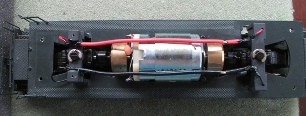
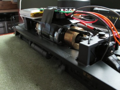
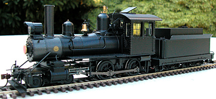
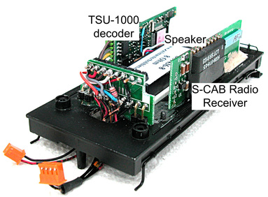
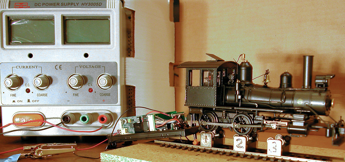
Steam loco tenders provide convenient space for batteries and decoders. However, wiring between tender and engine can easily become an untidy tangle making it difficult to separate engine and tender and sometimes restricting free movement of the tender's leading truck. A client (Bill) and I have jointly undertaken S-CAB conversion of a brass loco; he is re-motoring the loco and I'm responsible for installing a complete S-CAB system in the tender. We needed a connector between tender and loco and Bill suggested I look at SoundTraxx DBX-9000 wiring kit.
Picture
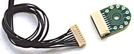
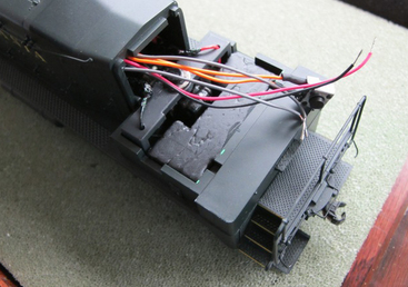
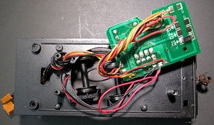
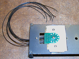
It provides a 9-pin socket and a compatible cable harness with wires that are thin, flexible and black. Nine wires is more than we need, but the unused wires are easily removed from the plug. Bill's project required only 5 wires; 2 for motor, 2 for headlight and 1 for right-rail pickup. I assigned pins in conformance with NMRA specs for a 9-pin JST socket. The center mounting hole fits a 2/56 screw. For installation, the first idea is to mount the DBX circuit board on the underside of the tender chassis.

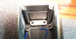
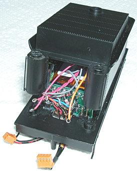
The flaws in this simple plan were soon apparent. The tender chassis (floor) is solid brass sheet, so we need insulation. We also have to cut a hole to route wires from inside to the underside of the tender. However, the show-stopper was insufficient clearance to accommodate the DBX between top of the  tender's leading truck frame and the tender floor above.

A Better Plan

Picture
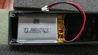
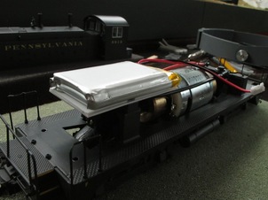
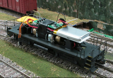
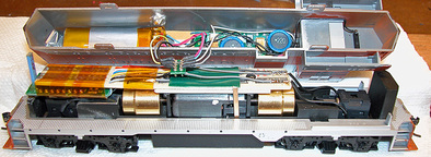
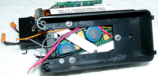
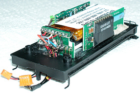
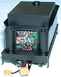
Mounting the DBX on top side of the tender floor is more complicated but has several advantages. Not only can the engine be unplugged from the tender, but the DBX, with wires attached, can be separated from the chassis, making it much easier to access most of the S-CAB components, which are mounted in the body of the tender. The speaker is the only item directly attached to the tender chassis.

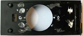
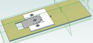
This installation required a rectangular opening in the tender floor, which I admit was tedious work. The DBX is mounted on a piece of styrene sheet which provides insulation from chassis and allows the DBX to be tilted downwards to unplug the engine cable harness.

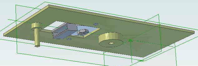
Here are top and bottom views from a 3D CAD design. If you have an up-to-date version of Adobe try this link to view a 3D file.
Picture
Picture

S-CAB Conversion of S-scale NW2 Switcher

8/24/2013

 
Introducing Peter Vanvliet
Peter models S-scale and has now converted three of his locos to S-CAB radio control with battery power. He has meticulously documented these projects on his own website and I invited him to summarize his first installation, the NW2 switcher, as a guest blog. He agreed, and what follows is his description with some Stanton editing. My apologies for skipping several of Peter's detailed explanations. Please visit his website for complete documentation.
Peter continues,
I have decided to convert this engine to use the S-CAB system, and to make it battery-powered. You can read about S-CAB in the article I wrote about it. The first step in any installation is to remove the body shell. I have a separate article on how to do that. After stripping all electronics, what remains is a motor, flywheels, truck drive shafts and wires for rail pickup. The first challenge is to determine locations for all S-CAB components and be able to replace the body shell with everything installed.
Picture
The battery:  I'm using NWSL's 1000 mAh battery and installed it first, because it's the largest component. As luck would have it, the battery fits width-wise in the shell and can lay flat against the shell roof in order to clear the mechanism that must fit below in final assembly. This requires the speaker to be removed.
Picture
Since the battery must be all the way up front against the two body shell mounting posts, plastic protrusions that held the speaker must be removed without damaging the body shell.
Picture
Next, a quick test to make sure the battery fits without bowing out the body shell. It's good!

Picture
I wanted to install a " battery shelf" mounted using two holes in the top of the truck mounting bridge. These were already tapped (from factory installation of the original circuit board). It was just a matter of cutting a piece of 0.040" thick styrene, drilling two holes, and mounting the "shelf" using the original screws. Since the screw heads are not recessed, I glued a second piece of styrene on top of the first one to create a flat surface for mounting the battery. The shelf sits above the truck mounting and "below" the top of the motor to make sure there is enough clearance to the top of the shell. To secure the battery, I spread some hot glue on the styrene, and quickly pressed the battery onto the glue, which sets in a few seconds. It turns out to be a solid installation, yet somewhat removable should the battery need to be replaced in the future.

Picture
The BPS circuit board: There is very little space above the motor and below the inside-top of the shell! The solution called for wrapping the motor with electrical tape and directly placing the BPS circuit board on top of  it. The issue with the BPS is the two inductors that are mounted on one side of the board. The other issue is that the way to turn on battery power is to wave a magnetic wand within 1/2" of a sensor, which means the BPS board must be close to the locomotive shell. So the BPS is positioned with the inductors (its largest components) facing down and the board pushed as far as possible toward the battery. The battery leads can then plug into the socket at opposite end of the board, with wires tucked to one side under the board. Since the motor fits snugly inside the shell, there is no space beside the motor except for a couple of layers of electrical tape.

Radio receiver and decoder: As you can see from the previous photos, we are running out of space in the engine's hood section. The cab interior and a substantial weight take up the cab's entire 3D space. So, the interior will have to go in order to make space for the decoder/receiver combo. It was actually quite difficult to get the cab off of the rest of the body shell, but it is possible. 
Picture
This is what is left after the cab interior has been removed. The weight is glued in place and is not removable without damaging the body shell. With the shell placed back on the chassis, there is a cavity where the decoder may fit! There's hope!

After studying the opening into the body, I realized that there is space above the motor mount and under the BPS circuit board. However, the heat-shrink wrap makes the combo too wide for the opening, although the circuit boards by themselves would fit. I eventually replaced the heat-shrink material with electrical tape, but first, I wanted to do a test install of the decoder/receiver and see if the system as it stands actually works.

Picture
I soldered the two gray wires from BPS board to wires connected to wheel pick-up (so that the battery can recharge from rail power, if present).  I covered the solder joints with liquid electrical tape. I then connected the red and black wires from decoder to BPS. Finally, I soldered orange and gray wires from decoder to motor. I ignored wires for lights for now.

And off to the layout I went. The track was not powered. I swiped the magnet wand over the sensor on the BPS board, turned on the S-CAB  throttle, and moved the speed control. The chassis started running smoothly, in both directions. 

Yippee! What a neat sight to see the engine running without rail power! I took a quick video and posted it on Vimeo (the chassis is running on my desk!!!) Next step, back to the work-bench.

Picture
To complete the installation, I cut a piece of 3/4" wide styrene and inserted it under the decoder and above the rear truck mounting bridge to keep everything away from spinning flywheels. After routing wires, I wrapped more electrical tape around these parts to hold everything in place.

Next, I connected the lights, snapped the cab back onto the body, put the engine on the track and tested it again paying attention to the LEDs. They looked good and they matched the engine's direction of travel.

At this point, everything was functional. However, there was one more part to install, the battery off switch.

Picture
The battery off switch: While considering possibilities, all of a sudden I had the idea of using the exhaust pipes. They are hollow and open into the body shell. My idea was to remove the push button from the orange wires of the BPS circuit, and solder them to two brass wipers. These are then going to be mounted under the two exhaust pipes. An external tool (shown in the photo) makes electrical contact to trigger BPS shut-down, just as the push button does. 

I put the engine on the track and tested the final set-up.  Everything worked great. I could turn on battery power by placing the magnet wand right behind the front exhaust pipe and operate the loco. When I am done running, I briefly insert my "exhaust pipe tool", and the battery is off! I love it! All with no external modifications to the engine.

Conclusion

I did find that it is easy to forget to turn off battery power, or to think it is off but it really isn't. Here's my process. Turn off track power, if present. Use the above mentioned tool (or the switch, if you use that), to turn off power from the battery. Then use the throttle and increase speed control. If the engine's headlight turns on or if the engine moves, the battery is not really off.

I tweaked some decoder CVs and got the engine to run nice and slow, while keeping its top speed reasonable for a NW2. As a stress-test, I ran the engine back and forth on my layout, which has about a 20-foot mainline. The headlight was on, but it was not pulling any cars. It was tedious, but I wanted to find out just how long a battery charge would last. I let the battery charge overnight so I was sure that it was full. I turned off all rail power and ran the engine purely on battery power, back and forth. I varied speed every so many runs, including maximum speed sometimes. The engine shut down just a few minutes short of THREE HOURS! Wow! The goal of this system is to have HO-scale engines run for one hour. It is fantastic that I got 3 hours out of it with an S-scale loco.

My next test was to see how this engine behaved on our Digitrax-powered club layout (the Houston S Gaugers). We had a one-day show. As my S-CAB article mentions, Neil indicated that the engine's drain on the battery is faster than the battery can be recharged. However, I figured that with the layout providing power and my home layout test showing three hours, I might get at least four hours operation out the engine. I started it with a 15-car train when the show
opened at 10am. At 4:30pm when we started to take our layout down, I turned off my engine. It had run the entire day! It never stopped, and it kept on running at one point when a short on the layout shut down the Digitrax system.

These two test results were way better than I had expected. I would have been happy if I could get a one-hour ride out of the engine on my home layout and maybe a two- to three-hour run on the club layout. This was fantastic. 

Battery Power on Western Pacific

8/20/2013


Introducing Steve Hayes

There are two reasons I invited Steve to describe his operational experience with S-CAB. He was an early user of the S-CAB system and wanted the system to solve real operational issues on his layout. His objective is prototypical operation of a model railroad and I figured a large layout with group operating sessions would be a serious test for S-CAB. For more info on Steve's Western Pacific layout, visit steveswplayout.hayeswp.com. Here is Steve in his own words.

History

Back in 1995, while designing my future Western Pacific layout, an important requirement was to escape the DC block system that had been used for many years. DCC was in its infancy at that time and while researching new systems I concluded DCC was still evolving and not yet ready for prime time.
The Western Pacific layout is designed for operation using a working Dispatchers Panel to control all turnouts and signals. Research lead me to the Chubb system that is basically a DC system with progressive block assignment. The selling point was the interface between dispatcher’s panel and signals. This system also did away with block switches. 
The Chubb system has served me well over the years, although it has its drawbacks compared with today’s DCC. I have always said DCC is the Cadillac of operating systems, but for me, it's weak link is rail contact for both power pick up and transmitting instructions to decoders. I have a constant problem with dirty track; why, I have not figured out. We changed all the rolling stock to metal wheels, which helped some. A friend, John Zach (www.sierrarailroad55.com) went DCC a few years ago and it has been very successful.
John and I alternate operating sessions every Thursday with 10 to 14 operators for about 4 hours. We also have out of town operators come in 3 to 4 times a year and we try to keep the railroads compatible so that when groups visit no one is sitting unless they want to. This is where a problem began to manifest itself. John uses Easy DCC and has 8 mainline throttles, but the Chubb system only supports 7 mainline throttles. We can both have unlimited tethered throttles (my yards) but I am restricted to 7 mainline throttles.
For years I have searched for a solution, mainly looking at some sort of battery power to add an eighth throttle and maybe find a solution to dirty track. The G scale folks with plenty of space have the answer. Now HO guys need to follow suit. A friend and I experimented with inexpensive race cars and cobbled up a working throttle system. This worked for just running trains but was not acceptable for heavy operating that we do on Western Pacific. I was aware of different people working on battery power. I joined all the groups I could find and watched and listened, feeling a solution was not far off.
Then I met Neil Stanton at the 2011 NMRA Train show and felt he was on the right track (pardon the pun) with his S-CAB system. I asked if he needed a Beta tester but, being a electrical engineer, he figured he did not need one. He
got one anyway, as I purchased a unit and started corresponding with him regarding S-CAB performance on my layout. I guess that is why he asked me to document some of my operational experience. He told me to be candid, which is really the only way I would want to proceed anyway, although he did reserve editorial control.

First Installation

So here we go, the first unit arrived and I set about installing it in a HO Intermountain A/B unit. The B unit was a dummy (as was the person installing it, I’ve been told) so I felt there would be few problems and this was basically true. I was an early-adopter and the first generation battery boards were too wide to mount flat and needed to stand on their edge, as did the battery. I wanted the capability of recharging from track power as I did not want to handle the loco when charging the battery. The BPS on-board battery charging is one of the real selling points of the S-CAB system. Looking at the width of the board, it appeared that 2 traces (printed wire paths) served no purpose, so I asked Neil if I could remove them. He asked if I knew what I was doing and reminded me about what happens to warranty when you take a grinder to a product. I assured him I would take responsibility, as I had experience building all the Chubb system boards.
Anyway, Neil must have been convinced because the latest BPS board is 3/4" wide. The dates of the boards, March 2011 and January 2012 respectively (visible in the photos), shows the evolution.
Picture
First-generation BPS - March, 2011
Picture
BPS Version 2 - the latest version
Installation was simple and I soon had the unit on the track for the first operating session. I have 4 unit trains that go from one end of the railroad to the other as straight through runs and felt this would be the best place to use the S-CAB as beginners usually run these trains and this would remove any locomotive assignment requirements. The procedure is run out with one train, wait a while and return with another; then repeat the run. The run is about 900 feet in length each way. With a dispatcher setting signals and loco using battery power, everything worked as designed except for two block signals that need direction of travel. Since the BPS has track power pickup for battery charging, track occupancy detection works, and signals drop as a train enters each block (remember there is no track power on my railroad except when a cab is assigned to the block). All went well, the light on-off function was a bit temperamental so we just left the light on.
My initial concern was the throttle, which I thought was too wide to hold comfortably in one hand while uncoupling cars etc. On the Yahoo group there was a complaint that it had a slider instead of a knob, but that has been no problem. In fact, I have found the slider beneficial. I toyed with putting a lanyard on the throttle in case it was dropped but it has not been a problem. I had problems with reliability of the original "magic" wand turning on battery power. I found it easier to turn the unit on at the start of a session with a 9 volt battery touched across the track. The latest magic wand works like a charm!
During the first session, the train went out and back and out again, then died on the return trip! (That's nearing the end of 3,600 feet run with a 12 car freight train and no battery charging). Talking with Neil, we decided to send him the locomotive for some testing of battery life. In the meantime, I installed a short section of track at each end of the railroad as a service facility with power so the locomotive could charge between trips. Since Neil added a second battery in the unit, I can’t report if my charging stations or the extra battery solved the problem. However, there have been no further problems.
It's important to remember to turn the unit off at the end of each operating session or it will draw the battery down. Neil had installed an off switch that I just press with a small wire. One thing we did was have the running lights tied into the track pickup so I can see it's charging. At the end of a session I put the unit on a charging track overnight so it's ready for the next session as I have been told not to leave it with a low charge.

Second Installation

Picture
My next project was to try to get S-CAB into a yard switcher. The new parts Neil supplied were smaller than the first one I purchased but I tried every thing I could think of to get it to fit. Even removed the front drive gears, but to no avail. So I came up with the cow and calf configuration. I hooked a calf up to the switcher and let the crew try it for 3 sessions to see if having two units would be a problem. Then I installed all the components in the calf. I used both the cow and calf wheel sets for pickup and that is where I went wrong. I blew up the decoder. I sent the unit to doctor Neil and he found the loco motor was connected to rail pickup through the loco frame. With DCC, the motor cannot be grounded to the frame and mine was! I asked Neil, how was I supposed to know that, and he has now written some bureaucratic instructions to make users aware of this condition.

With the switcher we had to use a smaller battery so my plan from the offset was to leave track power on in the yard as mainline trains stay on the siding and do not enter the yard (intentionally). As usual, if there is a weak spot, operators find it. With battery power, there's no buzz when the turnout is against you; you just end up on the ground! Well, one night every time I went by the yard the operator was putting the locomotive back in the track and I think this drained the battery. We have never had a problem since. One thing that happened was the yard operator left the yard turnout lined for the yard and the incoming train entered the yard, hit the 8 volt yard power and launched! I added a dead section to eliminate that problem.
With BPS, the yard is a pleasure to operate; no stalls. To explain battery power I say, "remember when you brought that brand new locomotive home and put it on the track and it ran so smooth". Well, with battery power and no need for track power, it runs even smoother than originally! 
I do not use the same throttle for multiple locos; each locomotive has its own throttle. I found while testing the switcher that the original unit took off because I forgot to enter the switcher's decoder address. I warned Neil that this would continue to be a problem and he provided a replacement chip with software changes so that each throttle switches on with a specific locomotive address already selected.

Third Installation

As with everything, the best made plans work for a while and then things change. It became apparent we could use another throttle as the Reno operator was using a tethered throttle to switch the yard and then switched over to a mainline throttle to go out on the main to Oakland. This required a panel switch to change from tethered to mainline throttle and we all know that the less “model railroad” we have the better.
Picture
So I sent a Kato GP35 to Neil to see if he could get the components into just the locomotive! Check it out on the website as he documented the work. One
might ask why I have Neil help with the installations. Well, it's twofold. One he does beautiful work and the other; I keep nagging him to get information out there with photos of what can be done. A picture is worth a 1000 words especially to those of us that are a bit skeptical of something new.

We ran the GP35 for the first time during a recent session. It switched the yard for about 30 minutes, then ran to Oakland doing some switching along the way. It then returned to Reno and finished up the switching there, all in all, about 2 ½ hours of running. I did not have the yard power on to recharge the battery while working the yard, but I plan to do this as a backup. The only thing we notice was there was occasional low speed creep. I'm sure there is a reason for this. Neil is usually pretty good about tracking and fixing these types of problems.  We are currently running 3 throttles. Two are used for switching the yards and one on the mainline. We have not noticed interference between them, although Neil tells me that low speed creep may be an indication of radio interference.

Conclusion

To sum it up, I could not be happier with the S-Cab system. As further development occurs, I expect components will become smaller and installation should be easier. Anyone starting out should give S-CAB a serious look. To build a railroad without wiring and not having to clean track has to be a big plus for newbie’s to the hobby. I strongly believe that this will become a future standard. Since it does not require those on DCC to upgrade, there is no worry about DCC through-the-rails becoming obsolete. As I said earlier DCC is the Cadillac of operating systems; now I can say, battery power with S-CAB is the Rolls-Royce!

On30 Bachmann 4-4-0 Conversion

8/11/2013

 
Picture
This loco was delivered with a non-sound, 2-function decoder installed in its tender and 6 wires between tender and engine. Our objective is to equip the loco with S-CAB radio control and battery power and upgrade to a sound decoder.

Since this model is already wired for DCC operation, no work is required on the engine. Sockets allow the engine to be unplugged and safely stored while all conversion work is performed in the tender.

The tender has a metal chassis and plastic body. Extra parts are included to model the loco as a wood, coal or oil burner. Mounting an oil bunker on top of the tender provides an excellent location for the BPS circuit board and leaves room in the tender for a larger capacity battery (more energy storage).

Clearing space in the tender

Picture
Removing 2 screws allows tender body and chassis to be separated, providing access to a circuit board that terminates engine connection wires and includes an 8-pin decoder socket.
There's no wiring diagram for this loco, but the circuit board gives enough clues to figure out which wires are motor, headlight and rail pickup connections. Engine connection wires are the only items reused in our conversion. Everything is removed from the tender and all mounting posts, etc. are cut from the chassis to give a flat unobstructed surface.
Picture

Arranging radio control components

Picture
There's a lot of stuff to fit in a small space and the last thing I want is a tangle of wiring that prevents successful re-assembly at the end of the project. An oval hi bass speaker in a rectangular enclosure is mounted by cutting the chassis round speaker opening to fit the rectangular enclosure so it is recessed slightly into the chassis floor. This allows the battery (not shown in the figure) to be mounted above the speaker enclosure.

Not visible in the figure is a styrene bracket to hold the battery and support vertical mounting of decoder and radio receiver each side of the battery. I've departed here from the usual arrangement of mounting decoder and radio receiver back-to-back.

To fit vertically, I had to shave (sand-paper) edges of the radio receiver board to make it as narrow as possible. The styrene bracket is screwed to the chassis; decoder and radio boards are mounted using epoxy putty, some of which is visible at the far end of the radio board below the antenna. Since the chassis is metal, I wrapped circuit board edges with electrical insulating tape before gluing with the epoxy putty. The wiring panel (which I anticipated would have to withstand some tagging and pushing during wiring) is mounted, never to be removed, with epoxy cement. The lower row of pins terminate connections to motor, headlight and rail pickup. The upper row provides connections for battery and BPS.

Installing battery power components

Picture
Picture
Picture
With minor trimming and removal of battery socket, the BPS board fits neatly in the oil bunker. Battery leads are soldered directly to BPS board. Styrene bits hold BPS securely. This location has two benefits: The magnetic sensor is flush against top of the oil bunker where it's easily actuated with a magnetic wand. It's also well-removed from the speaker, which has a strong magnet. Since there's very little clearance between top of battery and BPS board, wiring must be as short as possible, but not so short it prevents opening the tender.
As mentioned earlier, a standard BPS 850 mAh battery sits above the speaker and avoids use of stiff battery leads, which are impossible in this confined space. The short connections to left and right upper terminals of the wiring panel are easily unsoldered so the battery can be removed without disturbing any other components
Bachmann's design, with tender body swinging upward on rear edge plastic tabs, helps estimate length of BPS connecting wires. When tipped to about 30 degrees, body lifts off the chassis. The tender's removable front panel makes soldering BPS connections feasible by tilting body on it's tabs as photographed left. Looking carefully, wires are visible with soldered loops prepared ready for final terminal connections.
Picture

Picture

Testing

I always approach a complicated project with the pessimistic assumption that, if I don't test every step along the way, the end result won't be successful. There's nothing quite as frustrating as devoting hours of work on a loco, only to discover at the end, it does not work. In the photo above, radio control is being tested using a DC power supply without requiring battery or BPS. The latter combo was tested separately.

Conclusion

I'm quite impressed with how well this loco runs and quality of sound from decoder and speaker. In hindsight, a TSU-750 would have been adequate to handle motor load and installation would have been easier with a smaller decoder. At 12 volts and heavy load (my thumb on a driver wheel), the loco required approximately 200 mA. A smaller battery would have done the job, but extra storage never hurts. As a demo to amuse and confuse: sit the tender alone (no loco) on a table; turn it on with the magnetic wand, and send commands from an S-CAB throttle. The only thing we can't do is watch the loco move. All the sounds are there, including chuff.

Turning BPS On and Off

8/2/2013

 
To prevent a loco's battery slowly discharging when not in use, BPS includes an electronic switch to isolate the battery from all external components. I'll attempt to answer several questions related to how battery on/off is actuated.
Turn On
If a loco has rail pick-up connections, BPS turns on whenever track voltage is detected. If the loco has no rail pick-up or track is not powered, a magnetic sensor mounted on the BPS circuit board is actuated with a magnetic wand. This requires the sensor to be mounted where it's convenient to bring the wand within actuation distance (about 1/2 inch). Where it's not convenient to mount the BPS close to roof or side of a loco, a sensor can be separated from the circuit board and glued directly to a suitable non-magnetic surface using appropriate adhesive or epoxy.
Turn Off
BPS is designed to be turned off using a decoder function command, but differences in decoder behavior created so much confusion early in the life of BPS that a push-button is included as the default method of turn-off. The following discussion deals with turn-off procedures, but first, a few more remarks regarding the default push-button switch. Any momentary contact connecting (shorting) the orange colored wires is all that's required. A magnetic sensor (same component as used for turn-on) will work.
Another point to remember: Any charging input (from track pick-up or a charging socket) overrides turn-off. Neither push-button nor decoder function command will turn off battery power when charging input is present.
Turn-off using a decoder function command
Decoder function outputs control devices (lights, for example) by "grounding" the appropriate output. For example, a loco's headlight is connected to a decoder's white and blue wires where blue is positive common and white is the function output intended for headlight control. A decoder turns headlight on by connecting its white lead (thru a transistor) to ground.
Picture
Looking at the BPS, one of the orange leads is a ground connection; the other (call it the shutdown lead) performs turn-off. If a decoder function output is connected to the shutdown lead, a function 'on' command will ground it and turn off the battery, assuming there is no input charging power. When the battery turns off, everything shuts down, including the decoder, which is exactly what we want.

So where's the confusion?
When turned off, some decoders (NCE, for example) "remember" the state of their function outputs; others (SoundTraxx Tsunami, for example) forget function outputs and there is no confusion in this case. Shutdown using a Tsunami decoder is documented elsewhere.  
Confusion occurs when attempting to turn on a BPS that was turned off by a function command from a decoder that remembers its state during shutdown. Suppose the loco has no track power and the magnetic wand is used to turn battery on. As soon as the decoder starts, it turns on its remembered function output, which turns off the battery and everything shuts down. A user perceives this behavior as a BPS problem.
What happens if the loco has track power? In this case, track power overrides the decoder's function output and turn-on appears normal. However, the decoder will turn off battery power as soon as charging input is removed. To the user, everything is normal until the loco moves onto unpowered track and stops. Again, it looks like a BPS problem.
A turn-on procedure that always works
This procedure works because track power (charging input) overrides any attempt to turn off the battery. As soon as the decoder turns on, send a function command to turn off the remembered function output. That's it; no confusion, problem solved.
However, the situation without track power requires holding the magnetic sensor on (using the magnet wand in one hand) while using the throttle (in the other hand) to send a function-off command. Definitely not convenient.
Example
Here's an example based on a question from a modeler wanting to charge batteries while locos are idle in an engine shed or roundhouse where the building prevents manual access to turn battery on or off. A similar situation occurs with inaccessible storage sidings. For this example, the decoder is one that remembers its function outputs during shut down.

Since the most convenient time to charge batteries is at the end of an operating session, the loco, having completed its tasks, enters the engine-shed where rails are powered and power is on for battery charging. A decoder battery-off command is then sent to the loco and is executed by the decoder, but charging input keeps battery power on. After several hours of charging, loco-shed rail power is turned off and the decoder, with function output on from its previous command, immediately turns off battery power. This procedure reduces risk of forgetting to turn off the battery and later discovering a flat battery.

When commencing a new operating session, first turn on engine-shed track power, then transmit the appropriate battery-on (function-off) command and begin operation.

    Author

    I'm a retired electrical engineer, but still spending more time on engineering than on my layout. These days, it's mostly about applying radio control and battery power on smaller scale layouts (HO, On3, On30)

    Categories

    All
    Historical
    Installation Notes
    Loco Projects
    Operation

    The photo above is not my layout. It's a great view of Seattle's King Street station by Ross Fotheringham.

    Archives

    February 2019
    October 2018
    September 2017
    August 2016
    April 2016
    January 2015
    November 2014
    May 2014
    April 2014
    February 2014
    November 2013
    October 2013
    September 2013
    August 2013
    July 2013
    June 2013

    S-CAB Conversions:
    S-scale NW2 Switcher
    On30 D&RG 4-4-0
    HO-scale GP9
    HO-scale GP35
    HO brass 4-8-4
    HO Bachmann 2-6-2

    S-scale EMD F-40PH
    HO-scale ALCO DL-109
    On30 Forney
    HO-scale Atlas-Kato GP-7


Proudly powered by Weebly