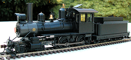
This loco was delivered with a non-sound, 2-function decoder installed in its tender and 6 wires between tender and engine. Our objective is to equip the loco with S-CAB radio control and battery power and upgrade to a sound decoder.
Since this model is already wired for DCC operation, no work is required on the engine. Sockets allow the engine to be unplugged and safely stored while all conversion work is performed in the tender.
Since this model is already wired for DCC operation, no work is required on the engine. Sockets allow the engine to be unplugged and safely stored while all conversion work is performed in the tender.
The tender has a metal chassis and plastic body. Extra parts are included to model the loco as a wood, coal or oil burner. Mounting an oil bunker on top of the tender provides an excellent location for the BPS circuit board and leaves room in the tender for a larger capacity battery (more energy storage).
Clearing space in the tender
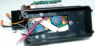
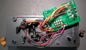 Removing 2 screws allows tender body and chassis to be separated, providing access to a circuit board that terminates engine connection wires and includes an 8-pin decoder socket. | There's no wiring diagram for this loco, but the circuit board gives enough clues to figure out which wires are motor, headlight and rail pickup connections. Engine connection wires are the only items reused in our conversion. Everything is removed from the tender and all mounting posts, etc. are cut from the chassis to give a flat unobstructed surface. 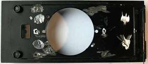 |
Arranging radio control components
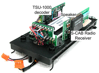
There's a lot of stuff to fit in a small space and the last thing I want is a tangle of wiring that prevents successful re-assembly at the end of the project. An oval hi bass speaker in a rectangular enclosure is mounted by cutting the chassis round speaker opening to fit the rectangular enclosure so it is recessed slightly into the chassis floor. This allows the battery (not shown in the figure) to be mounted above the speaker enclosure.
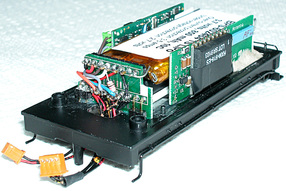
Not visible in the figure is a styrene bracket to hold the battery and support vertical mounting of decoder and radio receiver each side of the battery. I've departed here from the usual arrangement of mounting decoder and radio receiver back-to-back.
Not visible in the figure is a styrene bracket to hold the battery and support vertical mounting of decoder and radio receiver each side of the battery. I've departed here from the usual arrangement of mounting decoder and radio receiver back-to-back.
To fit vertically, I had to shave (sand-paper) edges of the radio receiver board to make it as narrow as possible. The styrene bracket is screwed to the chassis; decoder and radio boards are mounted using epoxy putty, some of which is visible at the far end of the radio board below the antenna. Since the chassis is metal, I wrapped circuit board edges with electrical insulating tape before gluing with the epoxy putty. The wiring panel (which I anticipated would have to withstand some tagging and pushing during wiring) is mounted, never to be removed, with epoxy cement. The lower row of pins terminate connections to motor, headlight and rail pickup. The upper row provides connections for battery and BPS.
Installing battery power components
  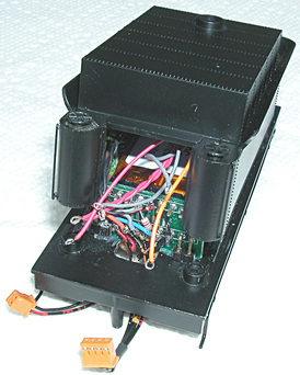 | With minor trimming and removal of battery socket, the BPS board fits neatly in the oil bunker. Battery leads are soldered directly to BPS board. Styrene bits hold BPS securely. This location has two benefits: The magnetic sensor is flush against top of the oil bunker where it's easily actuated with a magnetic wand. It's also well-removed from the speaker, which has a strong magnet. Since there's very little clearance between top of battery and BPS board, wiring must be as short as possible, but not so short it prevents opening the tender. As mentioned earlier, a standard BPS 850 mAh battery sits above the speaker and avoids use of stiff battery leads, which are impossible in this confined space. The short connections to left and right upper terminals of the wiring panel are easily unsoldered so the battery can be removed without disturbing any other components Bachmann's design, with tender body swinging upward on rear edge plastic tabs, helps estimate length of BPS connecting wires. When tipped to about 30 degrees, body lifts off the chassis. The tender's removable front panel makes soldering BPS connections feasible by tilting body on it's tabs as photographed left. Looking carefully, wires are visible with soldered loops prepared ready for final terminal connections. 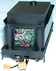 |
Testing
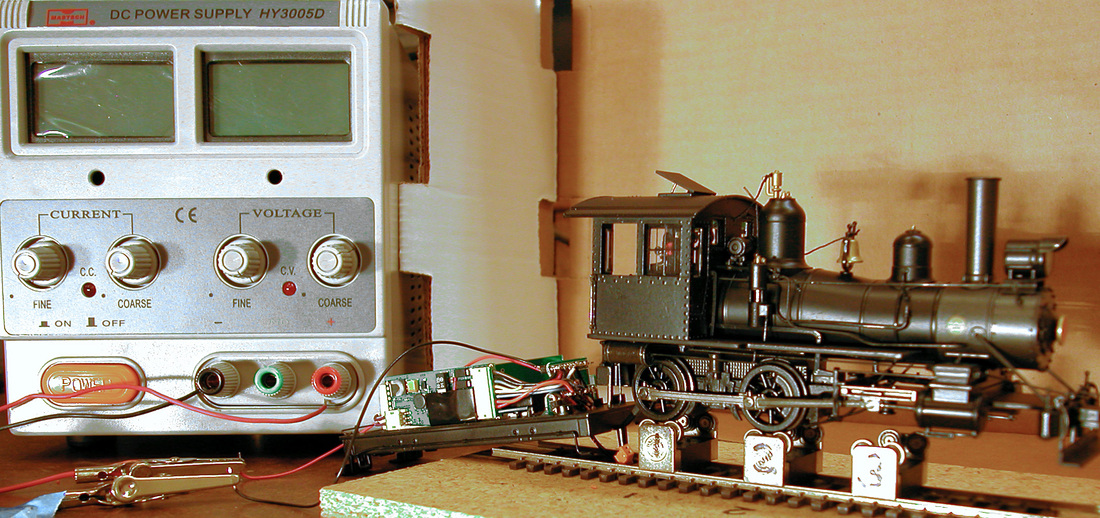
I always approach a complicated project with the pessimistic assumption that, if I don't test every step along the way, the end result won't be successful. There's nothing quite as frustrating as devoting hours of work on a loco, only to discover at the end, it does not work. In the photo above, radio control is being tested using a DC power supply without requiring battery or BPS. The latter combo was tested separately.
Conclusion
I'm quite impressed with how well this loco runs and quality of sound from decoder and speaker. In hindsight, a TSU-750 would have been adequate to handle motor load and installation would have been easier with a smaller decoder. At 12 volts and heavy load (my thumb on a driver wheel), the loco required approximately 200 mA. A smaller battery would have done the job, but extra storage never hurts. As a demo to amuse and confuse: sit the tender alone (no loco) on a table; turn it on with the magnetic wand, and send commands from an S-CAB throttle. The only thing we can't do is watch the loco move. All the sounds are there, including chuff.