Battery Power Supply (BPS)
 BPS-v4; 1 amp capability
S-CAB BPS is an integrated battery power supply using a 3.7 volt lithium-polymer (LiPo) cell to provide on-board power in small-scale locos or traction vehicles. It performs the following functions:
- Battery charging
- Battery on/off
- Battery over- and under-voltage protection
- Battery voltage step-up to 11 volt output
- Battery bypass when input power is available
- Overload protection
Versions
|
Both 1 amp and half amp versions of BPS are now available.
BPS-v4: 11 volts, 1 amp capability.
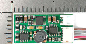
Size: 1.4”x0.7”x0.4” (35 x 17 x 10 mm) |
Half amp version is packaged in two configurations:
|
Product Recommendations
BPS-v4 is superior to to BPS-S. It's smaller, has twice the output, includes more robust protection and will eventually replace BPS-S. How soon this happens depends on acceptance of its $10 price premium over BPS-S. The improved performance of v4 is a result of several more expensive components used in its design.
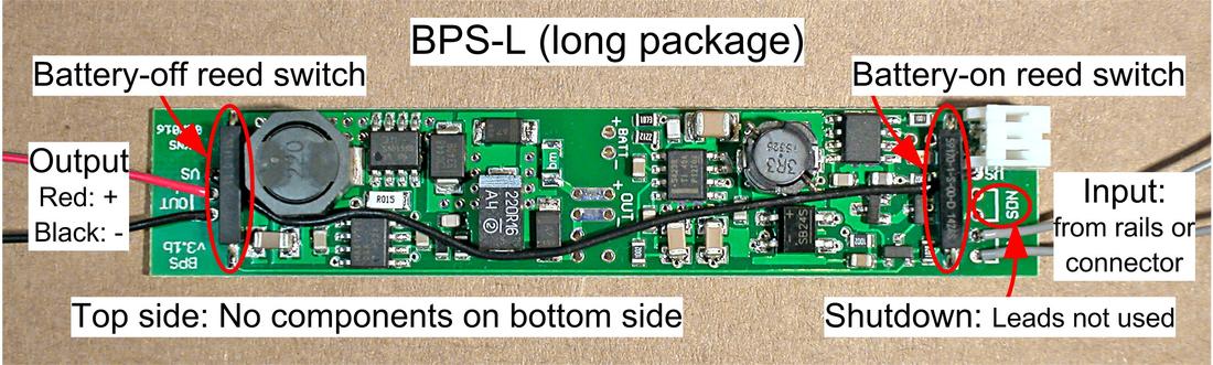
BPS-L is useful where it's 6 mm thickness is an advantage; flush against the side of a longer tender, for example. Or against the roof of a diesel loco with very little clearance above the motor. There is no one-sided configuration for BPS-v4.
Battery Charging
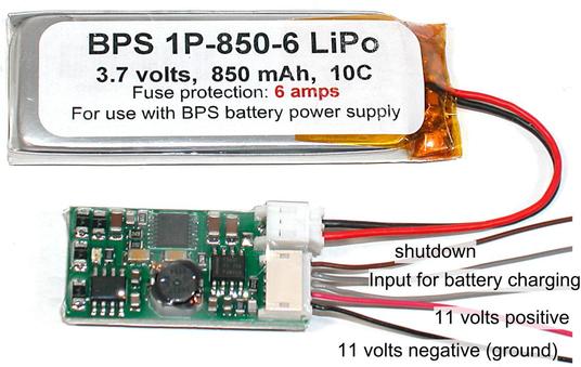
External power supply is from track pick-up or through a socket connected to "IN" terminals (gray wires). The power source can be DC or DCC so long as maximum voltage does not exceed 25 volts, but recommended value is between 12 and 13 volts. Battery charging occurs when input voltage exceeds 6.5 volts and charging rate is constant at approximately 450 mA, then decreases automatically to zero as battery approaches full charge (4.2 volts).
Battery Switch
An electronic switch within the BPS performs several functions; the most fundamental being to turn on battery power when beginning an operating session and off at the conclusion. It also provides over-discharge protection by turning off battery power when voltage drops below battery’s low voltage threshold.
Battery On: The battery switch turns on automatically when track voltage is sensed or can be closed manually by using a magnet to operate a magnetic reed switch mounted on the BPS circuit board. This requires the BPS to be mounted close to model roof or side (within 3/8”) where a magnet can reliably actuate the sensor. When this is not practical, a reed switch can be located wherever convenient and wired to the BPS.
Battery Off: A switch (normally open, momentary contact push-button or magnetic reed switch) connected to "SDN" terminals (brown wires) is used to shut down BPS and isolate the battery to prevent slow discharge when not in use. A decoder function output can also be used to perform shutdown.
Voltage Step-Up
BPS converts LiPo battery voltage, which varies between 4.2 and 2.5 volts, to an output voltage suitable for powering decoder and loco motor. By default, this voltage is 11 volts, but it can be customized when ordering a BPS to values between 8.5 and 12 volts.
Battery Bypass
What was previously an add-on modification is now included in the BPS design. With battery bypass, input voltage, which is rectified and used to charge the battery, is also connected to BPS output through a diode. If rectified input voltage exceeds BPS step-up voltage, BPS output is supplied from input power instead of the battery. In other words, the highest voltage (rectified input or battery step-up) supplies all or most of the BPS output.
Overload Protection
Two mechanisms provide overload protection;
- Above 500 mA, step-up electronics progressively reduces voltage to limit current output.
- A resettable fuse provides overall protection by limiting output to approx. 800 mA.
Input Over-voltage Protection
BPS-v4 includes protection against excessive input voltage, which turns off input when voltage exceeds 20 volts and restarts at 18.5 volts. Since protection is virtually instantaneous, voltage spikes, peaks, as well as sustained conditions are controlled. This is the main reason v4 is more robust than previous versions of BPS.
Connecting a BPS
 Wiring diagram for a non-sound decoder
Also applies for sound decoder with addition of a speaker.
Wiring diagram for a non-sound decoder
Also applies for sound decoder with addition of a speaker.
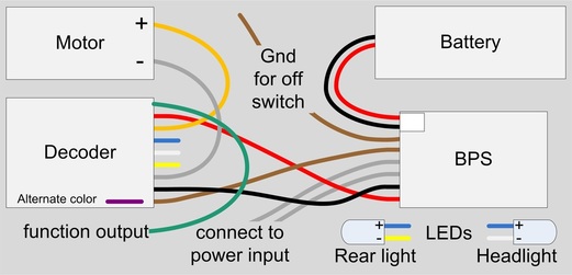
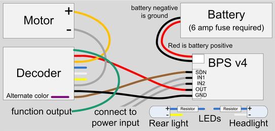
The diagram (figure right) shows wiring for a decoder with an NMRA standard 9-pin connector and wire colors that correctly match the DCC standard. Green and brown/violet wires are function outputs 3 and 4 respectively.
Since the S-CAB radio receiver is bundled with the decoder, it is not shown separately in the diagram.
Powering a decoder from a BPS requires the following modification of normal DCC decoder wiring.
For manually initiated shutdown:
For BPS-S: Connect both brown wires (active and ground) to a switch (reed switch or push-button).
For BPS-L and BPS-v4: No extra wiring is necessary since reed for shutdown is mounted on the circuit board
Since the S-CAB radio receiver is bundled with the decoder, it is not shown separately in the diagram.
Powering a decoder from a BPS requires the following modification of normal DCC decoder wiring.
- Connect BPS output (red/black wires) to decoder rail inputs (red/black wires). Polarity is not important.
- Connect loco rail pickup to BPS input (gray wires). Polarity is not important.
- BPS brown wires (SDN) are for battery shutdown and can be connected for two different shutdown methods:
For manually initiated shutdown:
For BPS-S: Connect both brown wires (active and ground) to a switch (reed switch or push-button).
For BPS-L and BPS-v4: No extra wiring is necessary since reed for shutdown is mounted on the circuit board
|
Warning: Since decoder blue wire is typically 10 to 12 volts, LEDs used for lights must be protected with a series resistor (2,200 to 4,700 ohms). |
|