Radio Control and Battery Power for Model Railroads
  • Home
  • Radio Control
  • Battery Power
    • Batteries Explained
    • Battery Care
  • Quick Start
    • Getting Started
  • Price List
  • Documents
    • Hints, Comments, Notes
  • Contact Us
  • Neil's Blog

Installation using S-CAB motherboard

2/24/2019


Introduction

The motherboard concept has been discussed elsewhere. It is intended to simplify installation of an S-CAB battery powered, radio-controlled system in small-scale locos. The purpose of this document is to report its application in a HO-scale Atlas-Kato GP-7. For brevity, we’ll skip the details and go directly to the result.

Ready to roll

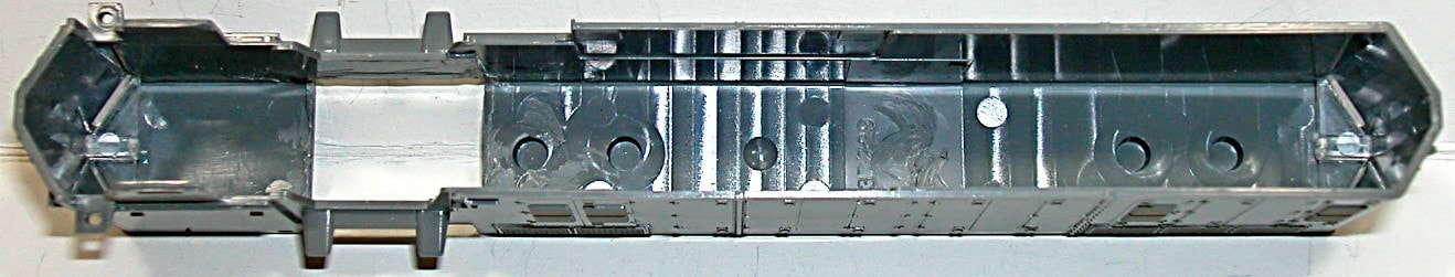
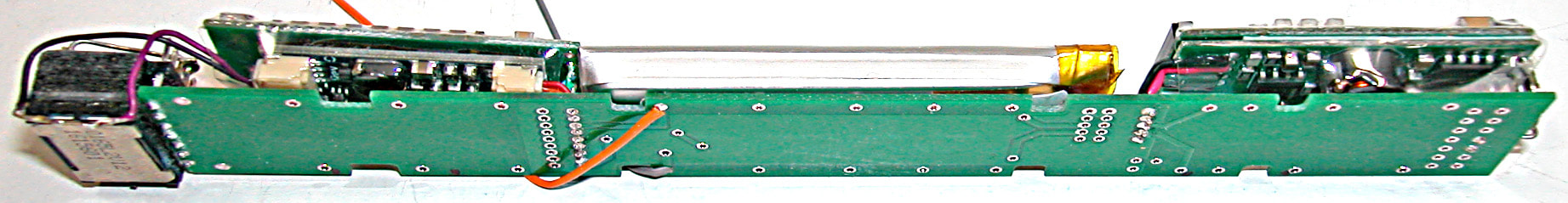
​This loco is ready to roll. All it needs is a body shell, which slides over the installation onto the chassis without much effort. It’s shown naked and annotated as an introduction to use of an S-CAB motherboard. 
Picture
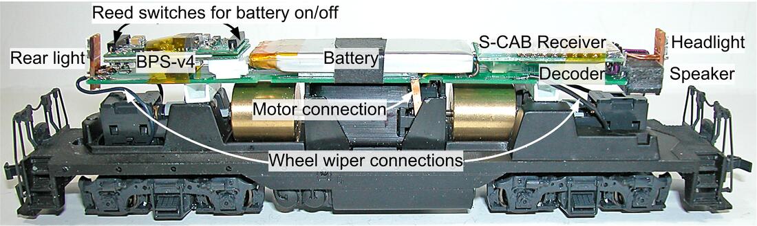
​For this installation, all components are mounted on the motherboard, including loco’s lights. This arrangement is a convenient characteristic of a GP-7 and other high-nose diesels. Consequently, no wiring connects to the body shell. 
​The motherboard assembly is completed and tested on the workbench. It is then mounted on the loco chassis and permanent connections made to motor and truck wheel wipers. Additional tests are completed before replacing the body shell. For example, does the forward direction command cause forward motion and operate the headlight.

Testing

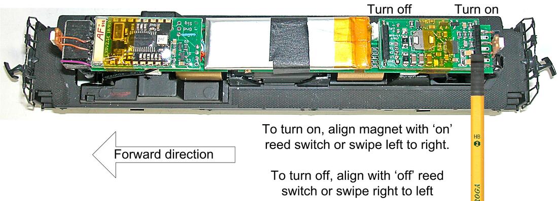
​No need to replace the body shell for a work-bench test-run. No need for track or power. Just turn on BPS battery power using a magnet wand and the loco (with or without shell) is ready to roll but be careful it does not end up on the floor.
Picture
​Aside from running off bench-top, this is a low-risk test. The motherboard was tested before making chassis connections and there is no external power source to cause trouble.
​A track test is higher risk. First, try it with no track power, which is not much different from a bench test, except the loco can be operated more thoroughly if its battery has enough charge. To test battery charging, turn on track power. This is the step where serious trouble can occur, which is a good reason to do it without the body shell. Common mistakes are forgetting to isolate motor terminals from loco frame, bad choice of power supply, shorted truck wipers, etc. 
​A green LED on BPS-v4 indicates if battery is charging. It's not obvious because the green LED is on the underside when BPS is mounted on the motherboard. The BPS is oriented so that reed switches are topside where they can be activated by a magnet wand. Another good test is turn off battery power (blue LED off) before turning on track power. BPS starts automatically when track power turns on.
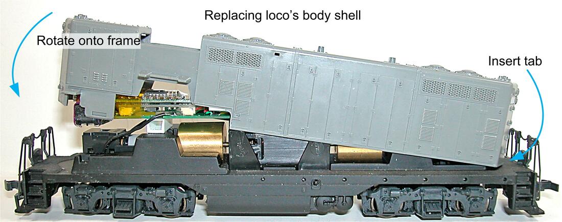
Replacing body

​This is a critical step in any installation. Will the lid close? The motherboard helps by enabling test fitting more easily throughout the project. Wiring clutter is eliminated, components don’t rearrange themselves by accident, and tight spots inside body shell can often be trimmed. The most difficult issue is headroom. Is there enough clearance above the loco’s mechanism for the motherboard assembly? This question must be addressed when planning an installation.
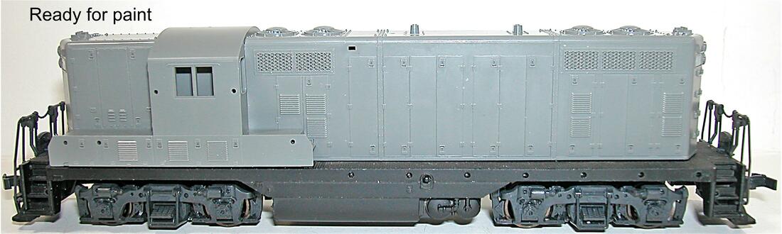
Picture

Done

Good news. The lid fits.
Picture

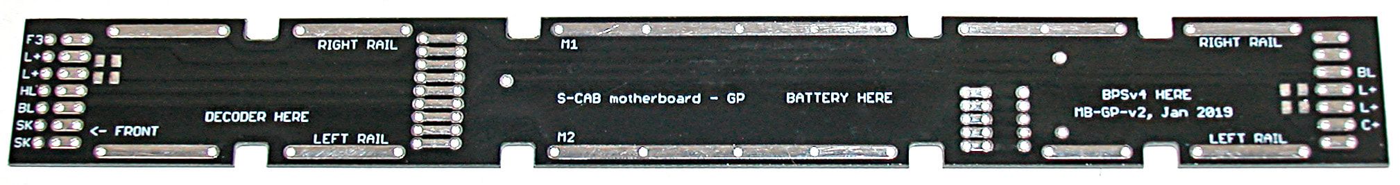
Motherboard Assembly

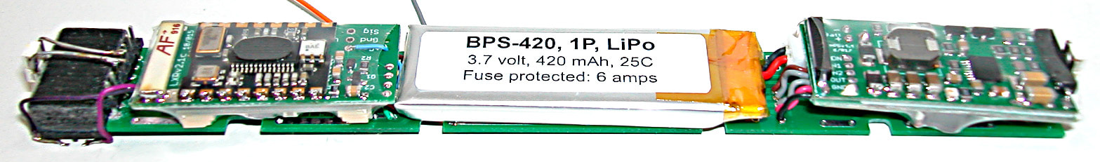
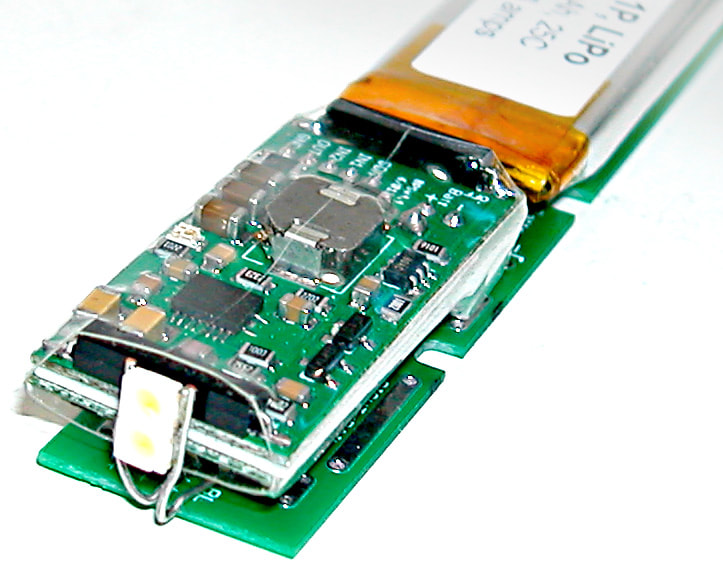
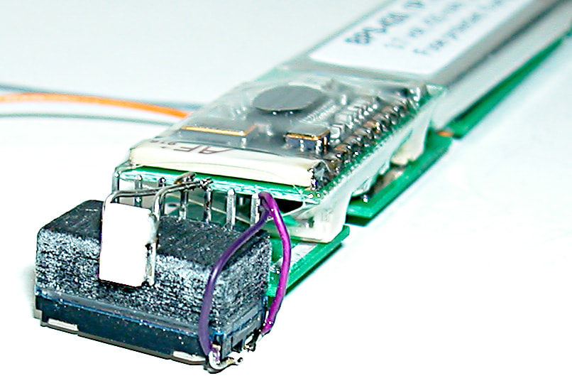
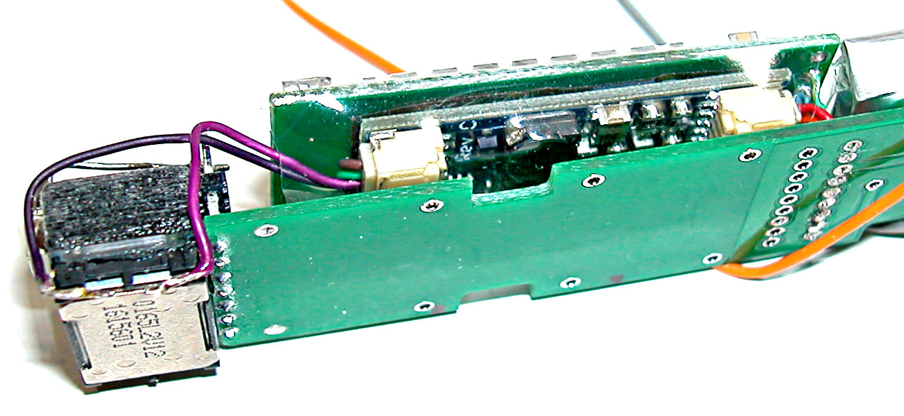
​The following components are mounted on the motherboard:
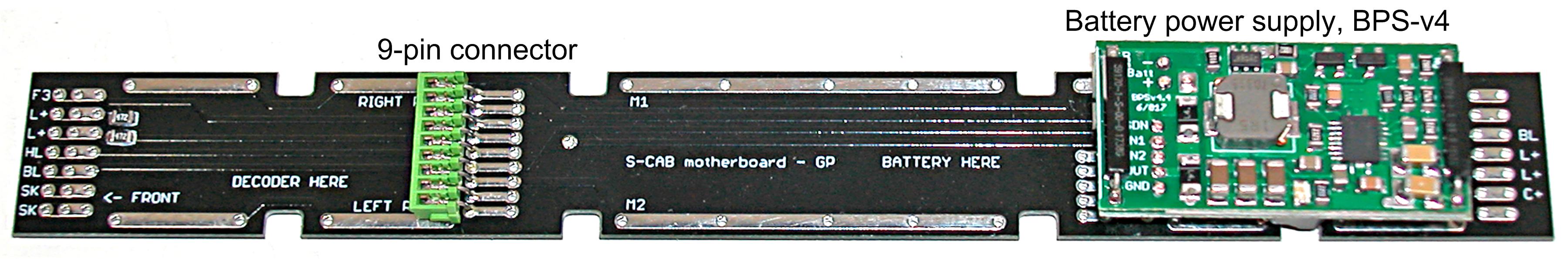
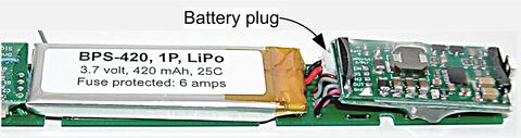
  • BPS-v4: Provides 11 volt power supply from 3.7 volt LiPo battery. Includes battery charging from track or other external power
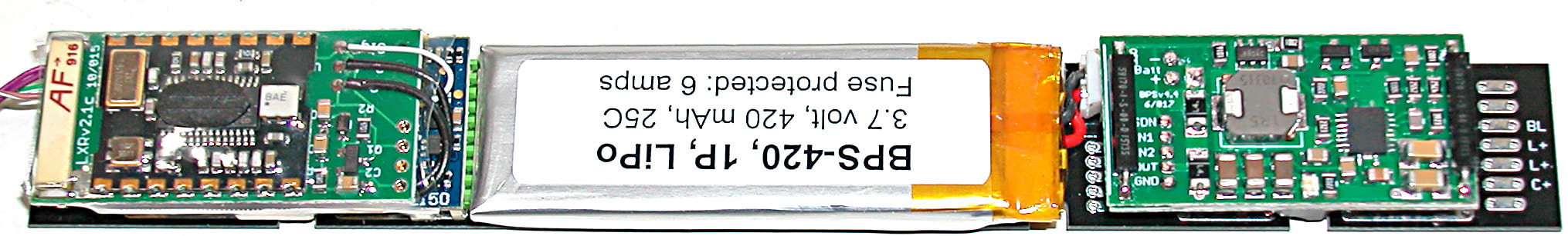
  • Battery: A 1P-420 LiPo cell with integrated 6 amp fuse
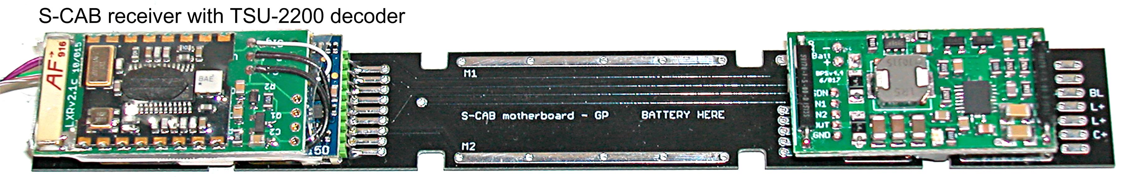
  • Sound Decoder: A SoundTraxx TSU-1100 sound decoder
  • Radio receiver: An S-CAB radio receiver integrated with decoder
  • Speaker: A 1 watt mini-cube
  • Head and rear lights: Surface mount LEDs with 4700 ohm resistor
With no components attached to the body shell, there is no wiring to prevent its removal. Easy preparation for painting this model is an immediate benefit. 

Maintenance

​Battery replacement: The battery is best secured to the motherboard by a removable method that does not leave a mess to clean up. Kapton tape is good and leaves no residue. Double sided adhesive tape is not recommended. When freed, lift the battery and lever its plug from BPS socket with tweezers or needle nose pliers. Since the battery leads are deliberately short (about ¾”) and the plug is tight, pulling by the battery may remove the battery and leave its plug stuck in BPS socket.
Picture
​If the loco’s mechanism needs maintenance, unsolder motor and truck pickup connections from the motherboard. If glued in place, there are 2 locations to pry loose and the assembly lifts off as a unit. If held in place by Kapton tape (author’s preference), cut and/or peel off the tape to remove the assembly.

Conclusion

​This installation was performed by John Lloyd in four identical models for a Canadian customer. The motherboard was designed to fit the GP-7 as well as a popular selection of North American diesel-electric locomotives. EMD GP, F and E class locos are good candidates. As we gain experience, the motherboard may be provided as basic, partial and fully assembled versions.

S-CAB Motherboard

2/22/2019


What is a Motherboard?

A motherboard is a circuit board onto which various sub-units ("modules") are mounted. Connectors and circuit traces on the motherboard facilitate modularity and eliminate wiring between modules.
Picture
MB-GP-v2: S-CAB installation motherboard
MB-GP-v2 fits a broad selection of HO scale, US style diesel-electric locos; EMD GP series, for example, often called "Geeps". It measures 0.67” wide, 5.75” long (17 x 146 mm), which is small enough for a GP-7 installation, yet large enough to accommodate a complete battery powered, radio controlled, ready-to-run system using commercially available DCC sound or non-sound decoders.
In addition to mounting BPS battery power supply, battery, radio receiver and decoder, the board ​includes terminals for external connections; track power pick-up, motor, LED lights and speaker. Depending on loco, lights and speaker can be mounted on the motherboard, which eliminates wiring connected to loco’s body shell and requires only 4 connections (power pick-up and motor) to loco chassis/frame. 

Assembly

​A 9-pin JST connector is provided for decoders with NMRA-compliant socket. No wiring harness is required. Decoders without a compliant JST socket require soldered connections and careful reference to decoder documentation. The BPS-v4 battery power supply can be mounted directly on motherboard (as in photo) or with a wired connection.
Picture
Add a decoder: This motherboard version requires either a SoundTraxx or NCE decoder with integrated S-CAB receiver. As shown in photo, no wiring is required for a SoundTraxx TSU-2200 decoder; just plug it in.
Picture
Plug in a battery: Depending on loco's space, 420, 800 or 1000 mAh batteries fit on the motherboard. If clearance between top of motor and roof interior permits, a 2P battery may be possible. However, 1P and 2P-420 are the only choices for HO scale, narrow-hooded GPs. The following photo includes a 1P-420 battery. Note the 3/4” battery leads, which will be default choice for batteries included with a motherboard installation.
Picture

Application

For HO models, application depends on the model’s prototype and its manufacturer. S-scale modelers should find the motherboard an easy fit. Fully assembled with a 1P-420 battery, the motherboard requires 0.44” (11.2 mm) headroom. Allow 12 mm (approx 0.5") clearance if using a 2P-420 battery. 
Models with limited headroom, motor mounted high on the chassis, for example, are not good candidates for this motherboard. Small yard switchers (SW series) in HO scale can also be eliminated as candidates. This still leaves a large selection of diesel prototypes for which this motherboard is applicable. However, creating unobstructed space can be a challenge. Factory installed circuit boards, over-sized metal castings, light-pipes, existing wiring and other clutter may have to be removed.

Example - Atlas-Kato GP-7 Installation

​This example used version 1 of the motherboard. ​No modification of loco chassis was required. The shell required some work. Light pipes were removed and interior of body shell decluttered. Lights and speaker were mounted on motherboard.
Picture
​The lens portion of light pipes was retained and glued into body shell.
Picture
Picture
​Components used:  TSU-1100 decoder, S-CAB radio receiver, 1P-420 battery, BPS battery power supply, mini-cube speaker, LED headlight and rear light.
Picture
Picture
Picture
Picture
Picture

NCE and SoundTraxx manufacture decoders referenced in this blog. Their proprietary rights, including product names, is acknowledged. 

    Author

    I'm a retired electrical engineer, but still spending more time on engineering than on my layout. These days, it's mostly about applying radio control and battery power on smaller scale layouts (HO, On3, On30)

    Categories

    All
    Historical
    Installation Notes
    Loco Projects
    Operation

    The photo above is not my layout. It's a great view of Seattle's King Street station by Ross Fotheringham.

    Archives

    February 2019
    October 2018
    September 2017
    August 2016
    April 2016
    January 2015
    November 2014
    May 2014
    April 2014
    February 2014
    November 2013
    October 2013
    September 2013
    August 2013
    July 2013
    June 2013

    S-CAB Conversions:
    S-scale NW2 Switcher
    On30 D&RG 4-4-0
    HO-scale GP9
    HO-scale GP35
    HO brass 4-8-4
    HO Bachmann 2-6-2

    S-scale EMD F-40PH
    HO-scale ALCO DL-109
    On30 Forney
    HO-scale Atlas-Kato GP-7


Proudly powered by Weebly