Introducing Peter Vanvliet
Peter models S-scale and has now converted three of his locos to S-CAB radio control with battery power. He has meticulously documented these projects on his own website and I invited him to summarize his first installation, the NW2 switcher, as a guest blog. He agreed, and what follows is his description with some Stanton editing. My apologies for skipping several of Peter's detailed explanations. Please visit his website for complete documentation.
Peter models S-scale and has now converted three of his locos to S-CAB radio control with battery power. He has meticulously documented these projects on his own website and I invited him to summarize his first installation, the NW2 switcher, as a guest blog. He agreed, and what follows is his description with some Stanton editing. My apologies for skipping several of Peter's detailed explanations. Please visit his website for complete documentation.
Peter continues,
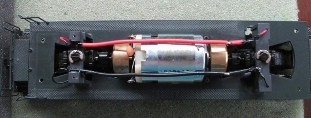
I have decided to convert this engine to use the S-CAB system, and to make it battery-powered. You can read about S-CAB in the article I wrote about it. The first step in any installation is to remove the body shell. I have a separate article on how to do that. After stripping all electronics, what remains is a motor, flywheels, truck drive shafts and wires for rail pickup. The first challenge is to determine locations for all S-CAB components and be able to replace the body shell with everything installed.
I have decided to convert this engine to use the S-CAB system, and to make it battery-powered. You can read about S-CAB in the article I wrote about it. The first step in any installation is to remove the body shell. I have a separate article on how to do that. After stripping all electronics, what remains is a motor, flywheels, truck drive shafts and wires for rail pickup. The first challenge is to determine locations for all S-CAB components and be able to replace the body shell with everything installed.
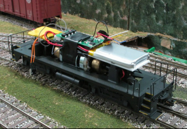
The battery: I'm using NWSL's 1000 mAh battery and installed it first, because it's the largest component. As luck would have it, the battery fits width-wise in the shell and can lay flat against the shell roof in order to clear the mechanism that must fit below in final assembly. This requires the speaker to be removed.
 Since the battery must be all the way up front against the two body shell mounting posts, plastic protrusions that held the speaker must be removed without damaging the body shell. | 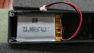 Next, a quick test to make sure the battery fits without bowing out the body shell. It's good! |
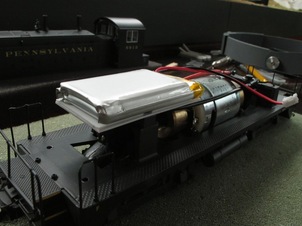
I wanted to install a " battery shelf" mounted using two holes in the top of the truck mounting bridge. These were already tapped (from factory installation of the original circuit board). It was just a matter of cutting a piece of 0.040" thick styrene, drilling two holes, and mounting the "shelf" using the original screws. Since the screw heads are not recessed, I glued a second piece of styrene on top of the first one to create a flat surface for mounting the battery. The shelf sits above the truck mounting and "below" the top of the motor to make sure there is enough clearance to the top of the shell. To secure the battery, I spread some hot glue on the styrene, and quickly pressed the battery onto the glue, which sets in a few seconds. It turns out to be a solid installation, yet somewhat removable should the battery need to be replaced in the future.
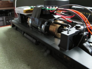
The BPS circuit board: There is very little space above the motor and below the inside-top of the shell! The solution called for wrapping the motor with electrical tape and directly placing the BPS circuit board on top of it. The issue with the BPS is the two inductors that are mounted on one side of the board. The other issue is that the way to turn on battery power is to wave a magnetic wand within 1/2" of a sensor, which means the BPS board must be close to the locomotive shell. So the BPS is positioned with the inductors (its largest components) facing down and the board pushed as far as possible toward the battery. The battery leads can then plug into the socket at opposite end of the board, with wires tucked to one side under the board. Since the motor fits snugly inside the shell, there is no space beside the motor except for a couple of layers of electrical tape.
Radio receiver and decoder: As you can see from the previous photos, we are running out of space in the engine's hood section. The cab interior and a substantial weight take up the cab's entire 3D space. So, the interior will have to go in order to make space for the decoder/receiver combo. It was actually quite difficult to get the cab off of the rest of the body shell, but it is possible.
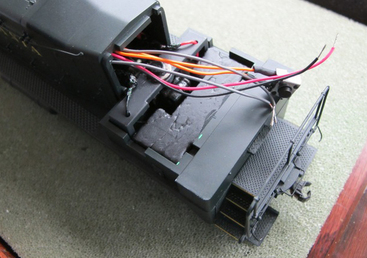
This is what is left after the cab interior has been removed. The weight is glued in place and is not removable without damaging the body shell. With the shell placed back on the chassis, there is a cavity where the decoder may fit! There's hope!
After studying the opening into the body, I realized that there is space above the motor mount and under the BPS circuit board. However, the heat-shrink wrap makes the combo too wide for the opening, although the circuit boards by themselves would fit. I eventually replaced the heat-shrink material with electrical tape, but first, I wanted to do a test install of the decoder/receiver and see if the system as it stands actually works.
After studying the opening into the body, I realized that there is space above the motor mount and under the BPS circuit board. However, the heat-shrink wrap makes the combo too wide for the opening, although the circuit boards by themselves would fit. I eventually replaced the heat-shrink material with electrical tape, but first, I wanted to do a test install of the decoder/receiver and see if the system as it stands actually works.
I soldered the two gray wires from BPS board to wires connected to wheel pick-up (so that the battery can recharge from rail power, if present). I covered the solder joints with liquid electrical tape. I then connected the red and black wires from decoder to BPS. Finally, I soldered orange and gray wires from decoder to motor. I ignored wires for lights for now.
And off to the layout I went. The track was not powered. I swiped the magnet wand over the sensor on the BPS board, turned on the S-CAB throttle, and moved the speed control. The chassis started running smoothly, in both directions.
Yippee! What a neat sight to see the engine running without rail power! I took a quick video and posted it on Vimeo (the chassis is running on my desk!!!) Next step, back to the work-bench.
To complete the installation, I cut a piece of 3/4" wide styrene and inserted it under the decoder and above the rear truck mounting bridge to keep everything away from spinning flywheels. After routing wires, I wrapped more electrical tape around these parts to hold everything in place.
Next, I connected the lights, snapped the cab back onto the body, put the engine on the track and tested it again paying attention to the LEDs. They looked good and they matched the engine's direction of travel.
At this point, everything was functional. However, there was one more part to install, the battery off switch.
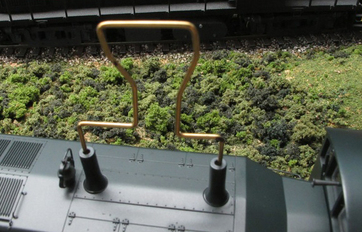
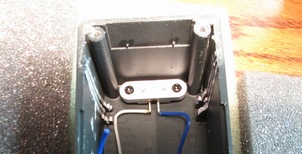
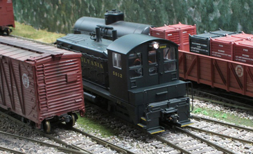
The battery off switch: While considering possibilities, all of a sudden I had the idea of using the exhaust pipes. They are hollow and open into the body shell. My idea was to remove the push button from the orange wires of the BPS circuit, and solder them to two brass wipers. These are then going to be mounted under the two exhaust pipes. An external tool (shown in the photo) makes electrical contact to trigger BPS shut-down, just as the push button does.
I put the engine on the track and tested the final set-up. Everything worked great. I could turn on battery power by placing the magnet wand right behind the front exhaust pipe and operate the loco. When I am done running, I briefly insert my "exhaust pipe tool", and the battery is off! I love it! All with no external modifications to the engine.
I put the engine on the track and tested the final set-up. Everything worked great. I could turn on battery power by placing the magnet wand right behind the front exhaust pipe and operate the loco. When I am done running, I briefly insert my "exhaust pipe tool", and the battery is off! I love it! All with no external modifications to the engine.
Conclusion
I did find that it is easy to forget to turn off battery power, or to think it is off but it really isn't. Here's my process. Turn off track power, if present. Use the above mentioned tool (or the switch, if you use that), to turn off power from the battery. Then use the throttle and increase speed control. If the engine's headlight turns on or if the engine moves, the battery is not really off.
I tweaked some decoder CVs and got the engine to run nice and slow, while keeping its top speed reasonable for a NW2. As a stress-test, I ran the engine back and forth on my layout, which has about a 20-foot mainline. The headlight was on, but it was not pulling any cars. It was tedious, but I wanted to find out just how long a battery charge would last. I let the battery charge overnight so I was sure that it was full. I turned off all rail power and ran the engine purely on battery power, back and forth. I varied speed every so many runs, including maximum speed sometimes. The engine shut down just a few minutes short of THREE HOURS! Wow! The goal of this system is to have HO-scale engines run for one hour. It is fantastic that I got 3 hours out of it with an S-scale loco.
My next test was to see how this engine behaved on our Digitrax-powered club layout (the Houston S Gaugers). We had a one-day show. As my S-CAB article mentions, Neil indicated that the engine's drain on the battery is faster than the battery can be recharged. However, I figured that with the layout providing power and my home layout test showing three hours, I might get at least four hours operation out the engine. I started it with a 15-car train when the show
opened at 10am. At 4:30pm when we started to take our layout down, I turned off my engine. It had run the entire day! It never stopped, and it kept on running at one point when a short on the layout shut down the Digitrax system.
These two test results were way better than I had expected. I would have been happy if I could get a one-hour ride out of the engine on my home layout and maybe a two- to three-hour run on the club layout. This was fantastic.