A Request
This innovation began with a customer inquiry. Richard is scratch-building an O-scale model in which he plans to install a Tsunami sound decoder. He wants to use S-CAB radio control and BPS battery power and operate the model on both his home railroad and his local club layout, which uses conventional DCC with wireless throttles. Since the club's wireless throttles operate at a radio frequency almost the same as S-CAB, radio interference prevents simultaneous use of both systems.
A Suggestion
I suggested we consider a dual control configuration to allow S-CAB battery power operation at home and use of the club's existing DCC system when operating on their layout. With this arrangement, Richard can operate with S-CAB at home, then switch to conventional DCC before taking the model to his club's layout where he can use one of their wireless throttles. Finding space for the necessary switch seems feasible in an O-scale model.
The configuration I will describe provides two methods of control as well as two power sources for the model; power from the rails when DCC is present and from the battery when there is no track power. No switching is required to implement the dual power source and the transition is virtually instantaneous making the model oblivious to track power glitches and interruptions. As a bonus; the battery charges while the model runs on track power.
Implementation
For readers interested in how it's done, I've included a diagram. For those who prefer to skip the theory and simply decide if it's something useful, I photographed the completed setup during work-bench testing. The required components (a diode, a resistor and a switch) are all wired on a simple circuit board, which is easily assembled by hand.
Engineering: It's useful to distinguish between DCC power and DCC signal. The former is supplied to the track and used to provide both power as well as communicate instructions thru DCC messages. In the decoder, track DCC is rectified to provide DC power supply and the DCC signal, with its encoded message, is separated and eventually finds its way to the decoder's microprocessor.
Looking at the schematic, left and right rail inputs go to both the BPS (for battery charging) and to the decoder thru it's black and red connections (consistent with NMRA standards). These black/red connections provide power to the decoder. Notice that the left rail input also connects to a resistor and from that resistor to a 2-way switch. The purpose of the resistor is to prevent track voltage passing thru the switch and destroying the decoder's microprocessor. The blue connection to the switch is DCC signal derived from S-CAB radio. Depending on switch position, the purple wire carries a DCC signal derived from either track or radio to the decoder.
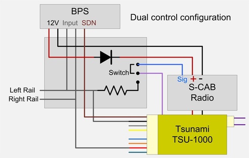
The BPS feeds power to the radio and decoder thru a diode, the purpose of which is to prevent back-feed to the BPS from the decoder's rectified track power. As a result of the diode, the decoder will be powered by the higher of rectified track DCC or 12 volt BPS output. The brown connection is Tsunami function F5 output, which is used to turn off battery power when the loco is not in use.
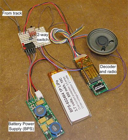
Application: Here is the system as it will be delivered to the client (with a smaller, better quality speaker) photographed while on the work-bench for testing. The decoder and radio is standard S-CAB conversion of a TSU-1000 decoder with one wire added to bring the DCC signal from the radio (blue wire) thru the switch and back to the decoder (purple wire). As viewed in the photo, switch left connects track DCC to the decoder; switch right connects radio DCC.
The BPS and battery are also standard S-CAB products. The perforated prototyping board is customized for this application. (A factory-made PCB could be much smaller.) Gray wires from rail pick-up are connected thru the circuit board to both BPS (gray wires) and the right/left rail (red/black) connections of the decoder's 9-pin JST socket. 12 volt supply from the BPS connects directly to the decoder thru a diode mounted on the circuit board. The battery has sufficient energy storage to serve as both primary (on home layout) and back-up power source (at the club).
Conclusion
Bench testing demonstrates that the configuration works exactly as expected. I hope, in a future blog post, to follow-up with a report of the client's experience, both at home and on his club's layout.
Acknowledgement
Tsunami decoders are a SoundTraxx product. The manufacturer's proprietary rights are acknowledged. Decoder modifications described herein are not endorsed or recommended by SoundTraxx and modifying a decoder voids manufacturer's warranty. However, I never deliver anything without thorough testing.