SoundTraxx has added Bluetooth (BT) radio communication to their TSU-2200 decoder. My initial reaction was to tell SoundTraxx I had no reason to buy or promote Blunami. S-CAB already added radio communication to SoundTraxx decoders and an S-CAB hand-held throttle was a more convenient way to operate model trains than using an Apple iPhone.
Then, I received an inquiry from an S-CAB user (I'll call him Bill) who had purchased Blunami and was impressed with the capability added by Bluetooth communication, particularly reading and writing decoder CVs (configuration variables); something that has always been a frustrating aspect of DCC. Bill wanted to operate his loco with S-CAB throttle but use his iPhone with Bluetooth for decoder programming and for demos in large railroading venues where radio interference can be a problem. He sent me his decoder and I decided to learn what I could about Blunami.
Background
I'll digress here with some background information that may help later in this blog.
Bluetooth: Bluetooth (BT) is a radio communication standard first proposed in 1996 by Intel, Ericsson, and Nokia to support short-range wireless connectivity and facilitate collaboration between different products and industries. The standard has evolved as technology improved and today, Bluetooth support is included in all popular mobile phones and most personal computers (PCs).
BlueRail Trains: My first contact from BlueRail Trains was January 2016 when they were working on FCC certification of their first Bluetooth product. I've been watching their progress for 7 years. Their collaboration with SoundTraxx and release of the Blunami product is a significant accomplishment.
U-Blox: U-Blox is a global provider of positioning and wireless communication technologies that
acquired Rigado’s Bluetooth modules business in July 2019. Since BlueRail's early development used Rigado's Bluetooth radio module, their firmware obviously carried over to the U-Blox chip that we find in Blunami.
SoundTraxx: Sophisticated radio communication has been added to the TSU-2200 decoder while retaining the option of standard DCC control. The magic is embedded in firmware within the U-Blox radio module.
Blunami
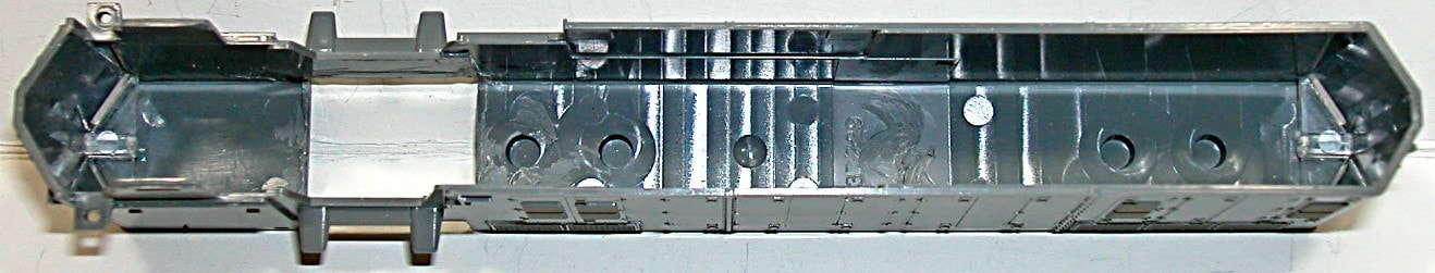
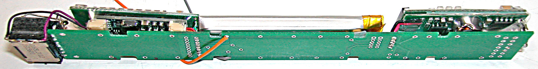
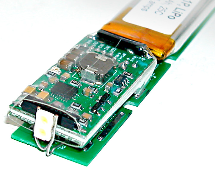
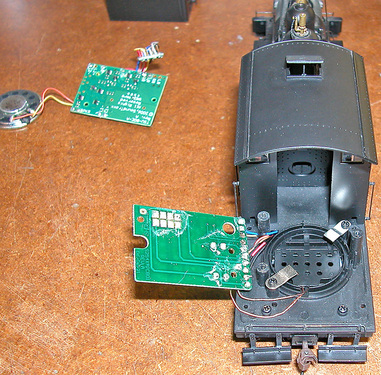
First step, remove the wrapper and void the warranty. Sorry Bill.
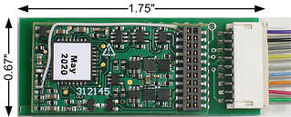
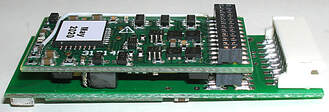
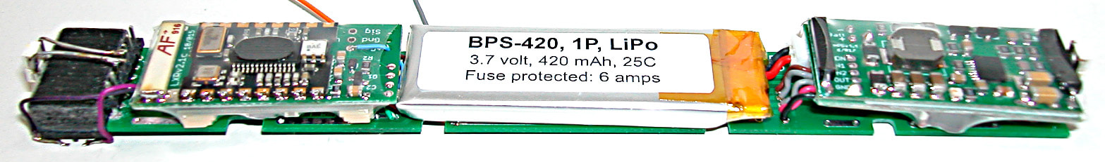
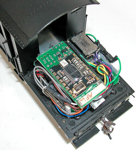
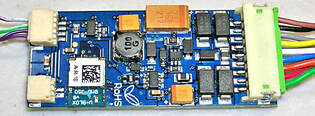 | 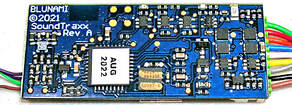 |
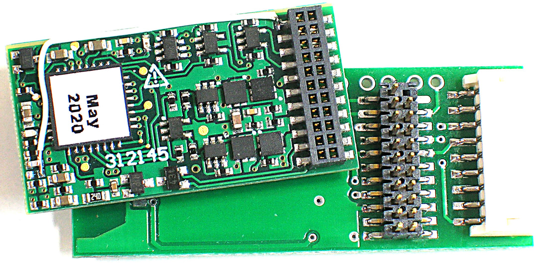
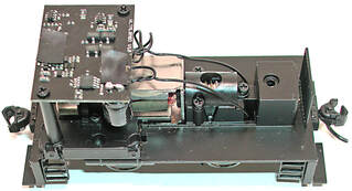
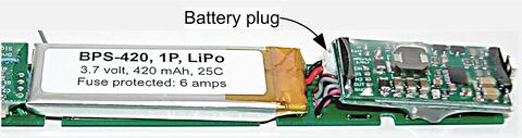
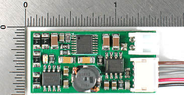
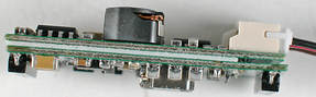
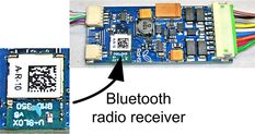 | Blunami circuit board looks like a TSU-2000 except for the addition of a small radio receiver produced by a company called U-Blox. As SoundTraxx explains, if no Bluetooth radio signal is detected, Blunami can be controlled by track DCC. If BT radio is detected, track DCC is replaced by BT communication. |
Adding S-CAB Radio
Why not replace track DCC with S-CAB radio input?
Similar to TSU-2200, Blunami should treat S-CAB radio input as if it is track DCC. The two radios work at different frequencies, so radio interference is not a problem and BT should prevail if both are detected, just as it does for track DCC.
Similar to TSU-2200, Blunami should treat S-CAB radio input as if it is track DCC. The two radios work at different frequencies, so radio interference is not a problem and BT should prevail if both are detected, just as it does for track DCC.
Testing
Rather than risk Bill's decoder, I decided to make peace with SoundTraxx and purchase my own Blunami. I checked with George Bogatiuk, who agreed, adding S-CAB radio to Blunami was feasible. Instead of using an Apple iPhone, I bought a refurbished 4th generation iPad for $60 on eBay. It's awkward to hold and definitely not a practical choice for hand-held operation, but the larger screen is nice for desktop tasks such as decoder configuration management.
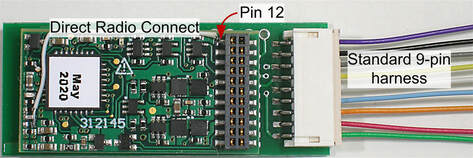
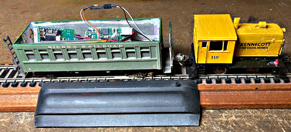
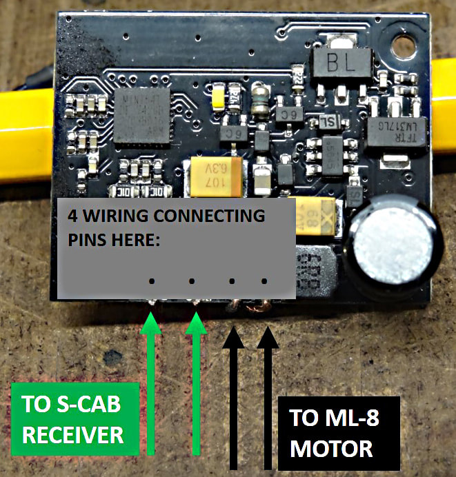
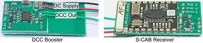
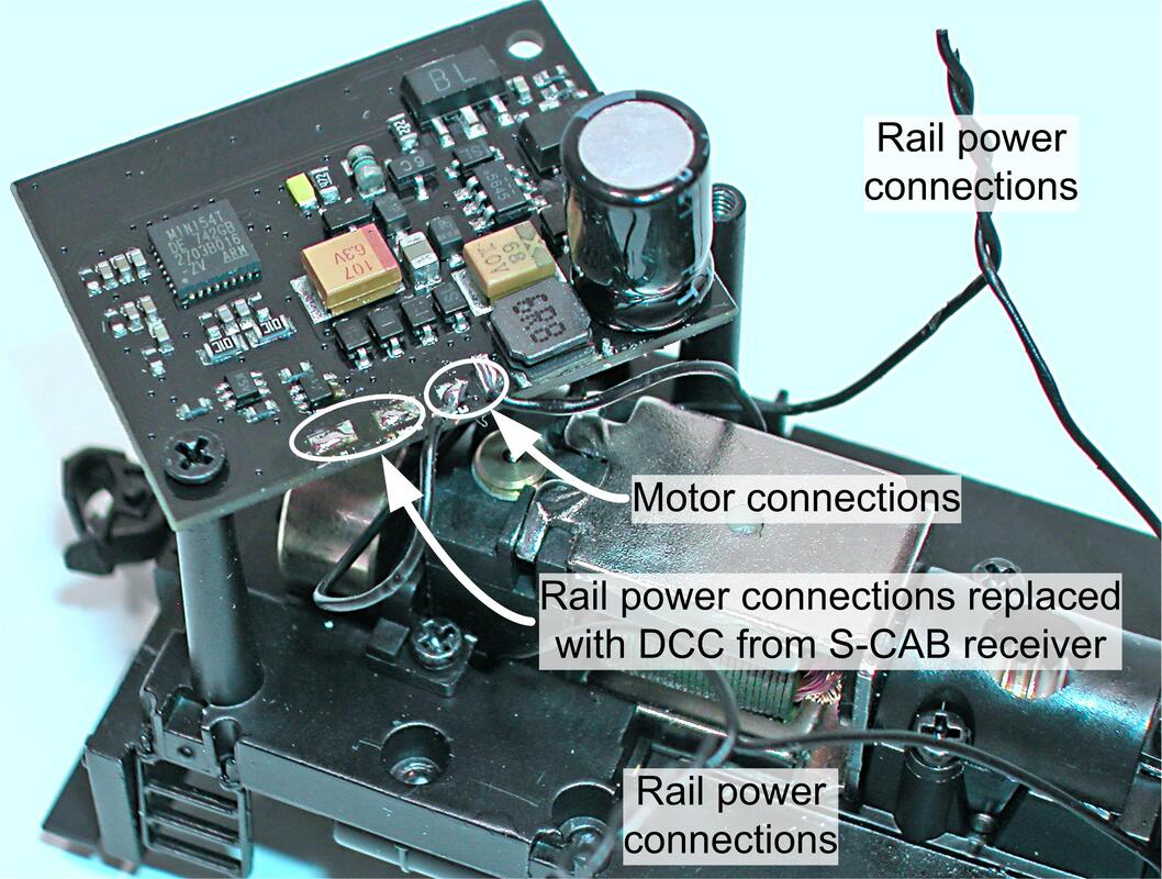
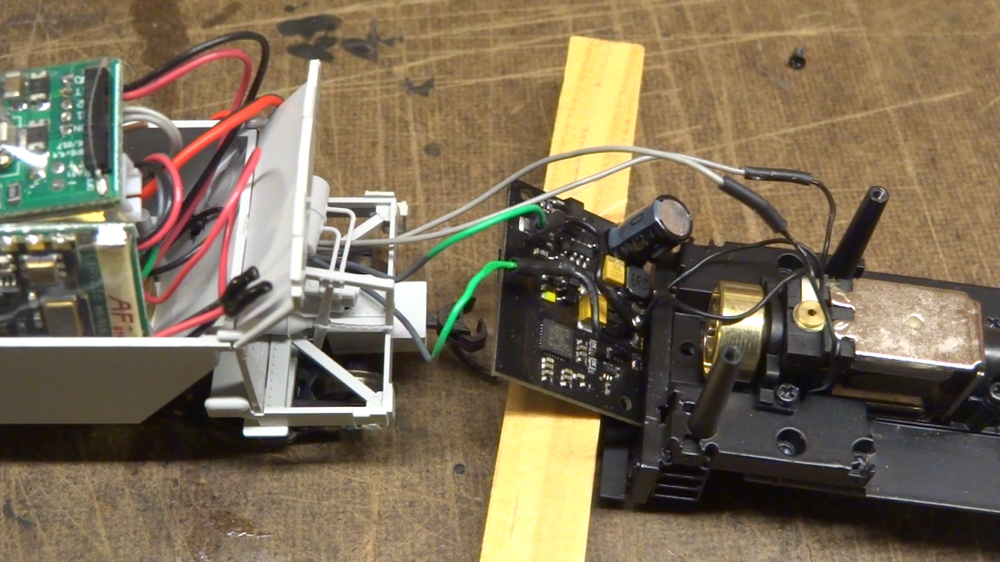
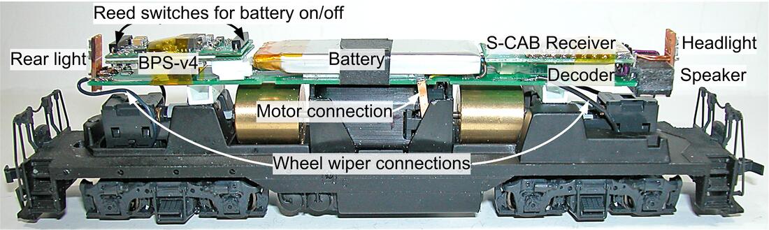
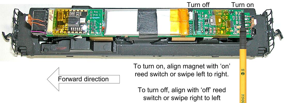
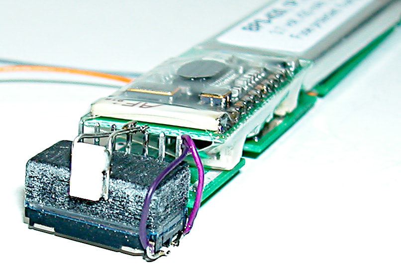
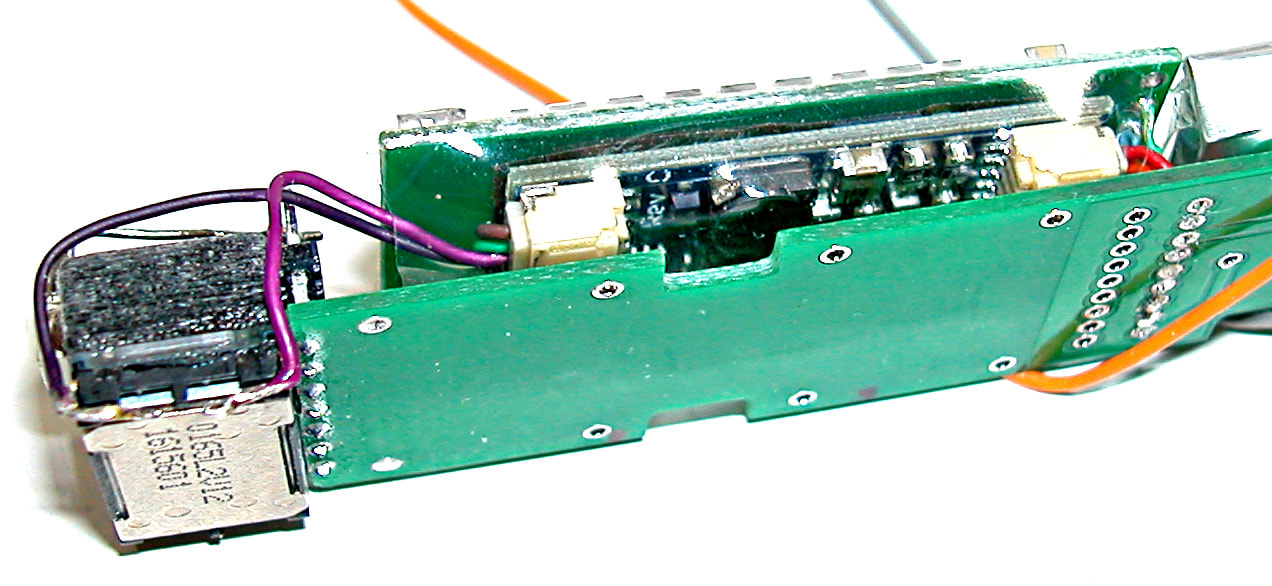
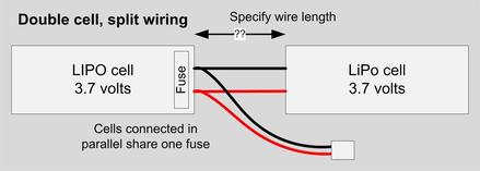
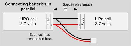
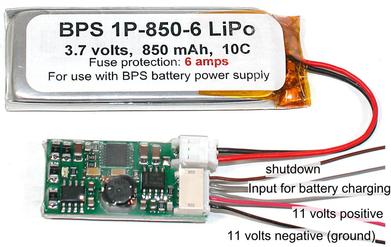
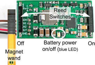
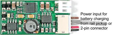
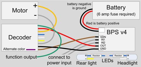
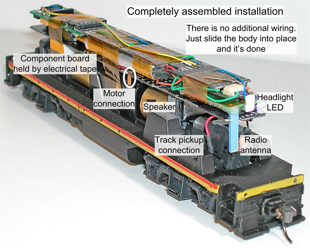
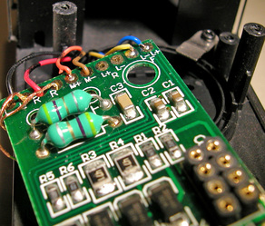
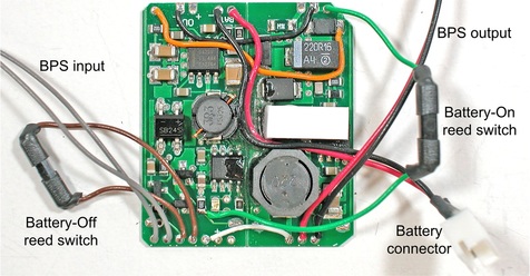
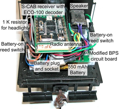
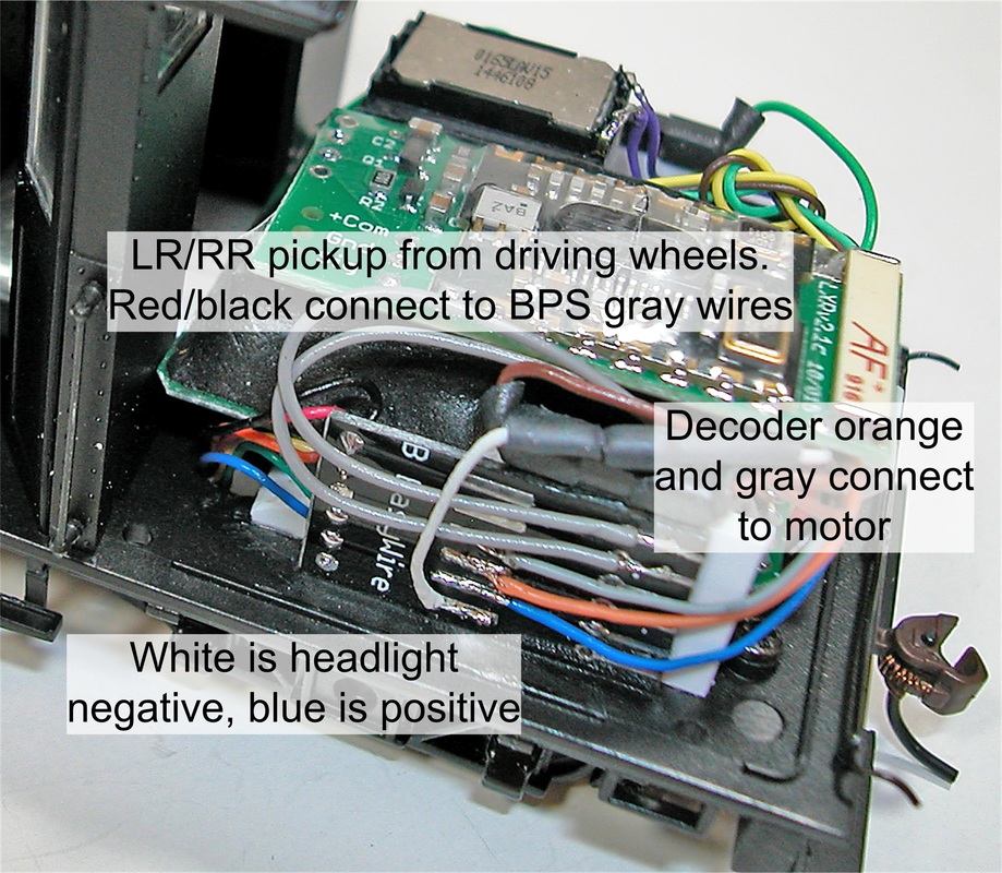
While waiting for iPad delivery, I went ahead with an S-CAB radio mod. exactly as done for a TSU-2200. This disables track DCC and replaces it with DCC signal from the S-CAB radio receiver. No functionality is lost because battery power disconnects decoder's rail inputs (red and black wires) and uses these connections for battery power supply. This eliminates any possibility of DCC communication from the track.
Conversion was successful. The S-CAB throttle operated Blunami. If S-CAB worked, Bill had agreed to buy a new throttle operating at 918.12 MHz, which avoids interference with NCE wireless throttles (the most common source of interference at train shows). 918.12 MHz is also compatible with CVP Products T-5000 throttle.
Starting the refurbished iPad required an Apple account and the usual new computer setup tasks. That done, downloading and installing BlueRail's Blunami train control app from Apple store was trouble-free. However, the app will not run on old versions of Apple's iOS operating system. It will run on iPhones and iPads with iOS version 9 and later. It cannot be installed on Android devices.
To avoid confusion, "Blunami" will be used as decoder name. I'll refer to the Blunami app as "iPad app".
To begin tests, S-CAB throttle was turned off. Would iPad app find and connect to battery powered Blunami that had been modified for S-CAB radio?
- The answer was yes. The iPad app connected when decoder battery power was turned on.
- Decoder data was displayed and there was an opportunity to enter loco name and define a few loco characteristics.
- Control commands worked.
- Decoder CVs could be viewed and edited.
- The iPad app saved decoder data.
- When S-CAB throttle was turned on, nothing happened. S-CAB commands were ignored and iPad commands continued to work without problem, as specified.
- When iPad was turned off, S-CAB did not automatically take control of the decoder.
- However, S-CAB throttle did gain control when the Blunami was rebooted (power off, then on).
- When Blunami app. was turned on, it eventually connected and took control away from S-CAB.
At this point, convinced that S-CAB worked with Blunami and did not interfere with Bluetooth capability, I converted Bill's decoder and investigated CV programming, which took me deeper into the iPad Blunami app.
Working with iPad App
SoundTraxx website has decoder documentation but virtually no documentation for the Bluetooth app. That's expected, since BlueRail Trains, not SoundTraxx, is responsible for iPad app. BlueRail's website has good information for older products, some of which is applicable to Blunami, but lacks up-to-date documentation. BlueRail's user interface is reasonably intuitive and help customizing the user interface was quick and easy.
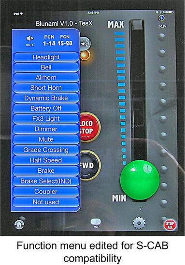
SoundTraxx decoders support flexible assignment of decoder functions to throttle buttons (physical keys). On iPhone or iPad, buttons are screen images, which BlueRail depicts as tabs with labels corresponding to SoundTraxx default assignments. For backward compatibility and consistency of different decoders, S-CAB uses button 5 for battery-off command. For SoundTraxx decoders, this requires that button 5 be mapped to decoder function FX4. For decoders with diesel sounds, SoundTraxx uses button 5 for a command to increase prime mover speed sound and BlueRail displays the tab with "RPM+" as its label. When asked the question, David Rees at BlueRail explained the simple method used for editing function tab labels.
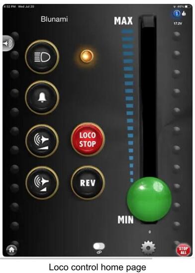
Function tabs are accessed as a slide-out menu from left side of the loco control home page. An additional swipe right drags a duplicate set of editable tabs into view.
Bill was not concerned by loss of RPM+ and RPM-. These tabs alter sound to simulate prime mover speed changes, but do not affect loco motion.
All CV programming to change function mapping was done with the Blunami app.
Conclusion
Contrary to my initial response, I will support Blunami decoders and offer them bundled with S-CAB radio. BlueRail's app solves the problem of reading CVs while operating on battery power. It is an excellent tool for managing decoder configuration and tuning performance. By adding S-CAB radio, users can combine the best features of both technologies. Bluetooth for configuring the decoder; a hand-held throttle for operating trains.