The Model
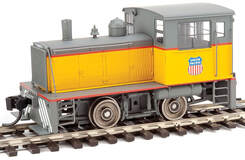
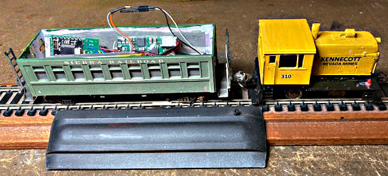
Walther’s HO model of a Plymouth industrial switcher is small. It was initially offered as a DC version and later as DCC-only. A circuit board mounted in loco cab roof includes motor control and lights. The DCC version is an ESU non-sound decoder, which makes an easy conversion to S-CAB battery power and radio control.
We have examples by two S-CAB users. Steve likes sound, Stan prefers non-sound decoders. After some initial confusion, Steve realized he had started with a DC version and, too late, we realized Stan began with a DCC-only version.
We have examples by two S-CAB users. Steve likes sound, Stan prefers non-sound decoders. After some initial confusion, Steve realized he had started with a DC version and, too late, we realized Stan began with a DCC-only version.
Steve’s Installation
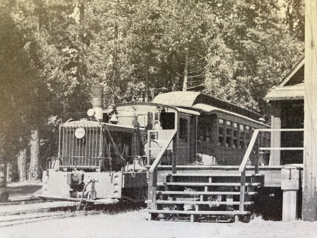
| This model has a neat decoder installed in roof of drivers cab but, for battery power, it needs a trailing vehicle to carry a battery. As Steve points out the following "battery car" can be any box car, passenger coach, covered hopper, loaded gondola, or loaded flat of any choice. He selected a historical prototype totally in character with his layout. As Steve explains: for this Installation I choose to model the last passenger excursion train on the Hetch Hetchy Railroad. It took place on May 25th, 1947 when members of the Railroad & Locomotive Historical Society road in Sierra Railroad passenger car # 6 behind HHRR Plymouth locomotive #1171 from Groveland to Mather CA and return. This 64+ mile round trip took place over rails that had been all but abandoned for several years and proceeded into some of the most wild and dangerous landscapes in the country. If anything had happened to the equipment the participants would have had to walk out from the wilderness of Yosemite National Park without benefit of phone lines or paved roads. | Since Steve was converting a DC version of the model and planned to install a sound decoder, the factory-installed circuit board initially appeared of little use except as a convenient way to make connections. A BPS-v4 battery power supply, battery, sound decoder, speaker and S-CAB radio receiver would all be installed in the passenger car. Steve continues, Once the cab shell is removed, the front edge of the cab circuit board shows four terminals labeled TRKL (Track Left), TRKR (Track Right), M+ (Motor +) and M- (Motor -). Six wires from the loco end up in a bird’s nest just under the board. To unravel this mess, remove one screw holding the circuit board and loosen the other so that the board can be twisted counterclockwise. Four wires are rail power pickup, two from each wheel set, and two are motor connections. Since battery power will be substituted for track power, the 4 wires between wheels and circuit board can be removed. Rail power is used for battery charging but I chose to use passenger car trucks for power pick-up and avoid having extra wires from loco to the following car. Two wires from the decoder must be connected to the loco's motor. Connect decoder orange wire to the wire going to motor from M+ and decoder gray to wire going to motor from M-. (Hint: If loco runs backwards in response to a forward command, reverse the connections.) I used a TCS two wire mini connector with leads of sufficient length that the actual connection was made well within the space in the following car. This allows simplifies connect or disconnect of the loco. Previously on other models I had attempted to connect in the space between loco and following car as that is where the brake line would be connected. That turns out to be difficult. Not only is space severely restricted but when attempted the cars tend to tip over or uncouple. Lastly, the simplest way to recharge the battery is to install one or two trucks on the following car that have power pick up from the rails. The leads from these trucks are then connected to the gray wires on the Battery Power Supply. |
Another reason for not discarding the model’s circuit board is two tiny LED’s on the cab roof that function as forward and reverse lights. These somehow continue to work even without attaching any wires from the decoder. And that’s it. Simple, fast, clean and runs like a top.
Stan's First Installation
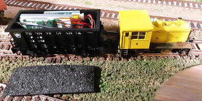
As mentioned earlier, Stan was too far into his first installation before he and I realized he had started with a DCC version and could have used the factory-installed decoder. He actually used an NCE D13J decoder bundled with an S-CAB radio receiver together with a BPS battery power supply all installed in a trailing coal car. He describes his installation in the following video.
https://youtu.be/ryinlRLmx9A.
https://youtu.be/ryinlRLmx9A.
Stan's Second Installation
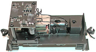
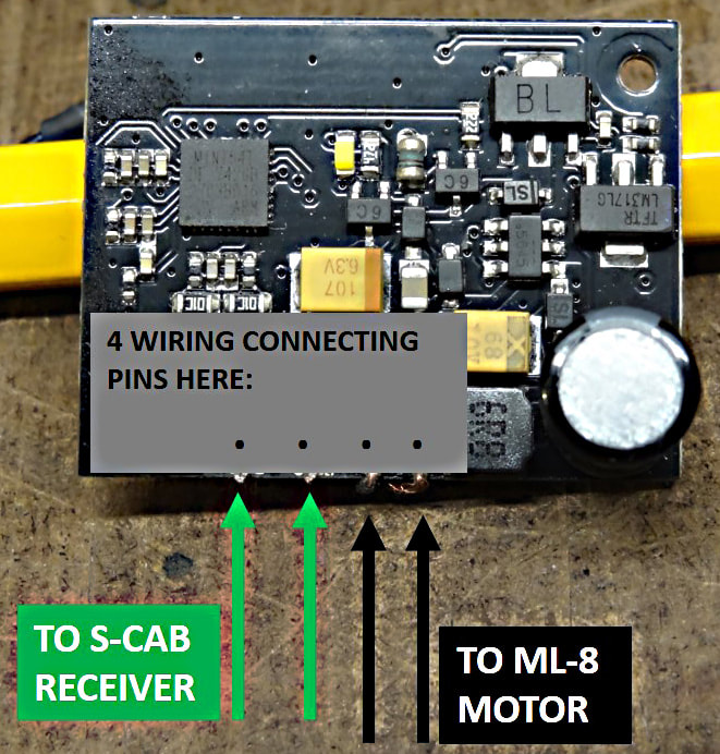
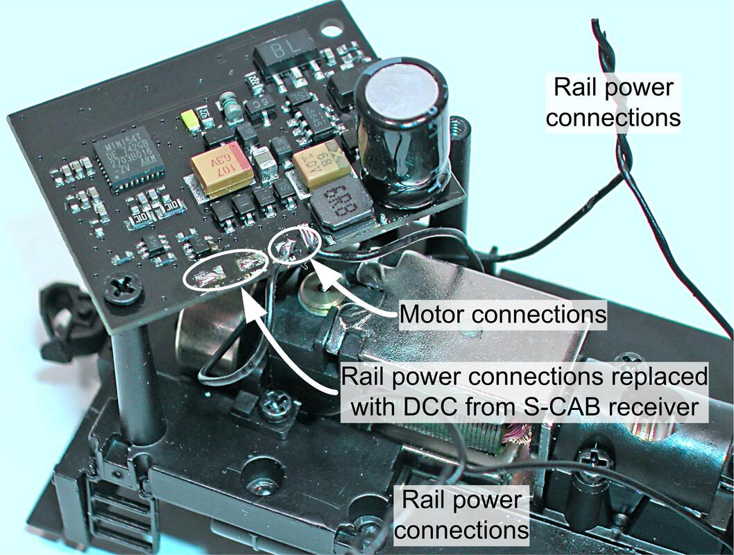
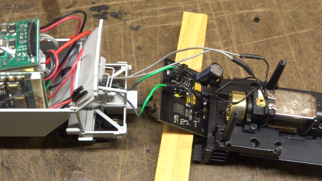
| For illustration to right, the decoder board has been temporarily mounted upside down. Wires from loco wheels (track power pick-up) have been disconnected from the loco decoder board and will be replaced with DCC connections from the S-CAB radio receiver. No change is required for motor connections. | This installation uses the factory-installed decoder by adding a DCC booster to the S-CAB radio receiver. As far as the decoder is concerned, the DCC booster output is no different to DCC received from the track. The loco's rail power connections can be removed or rerouted to the battery car. As Steve observed, this requires 4 wires between battery car and loco, but it eliminates the need for battery car trucks with power pick-up. Video: https://youtu.be/nNyWBvL73D0 |
