Introduction
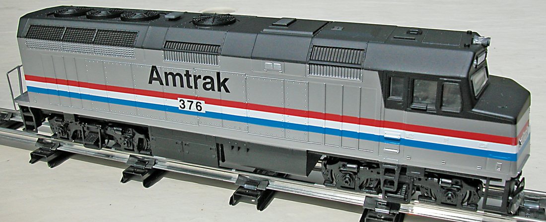
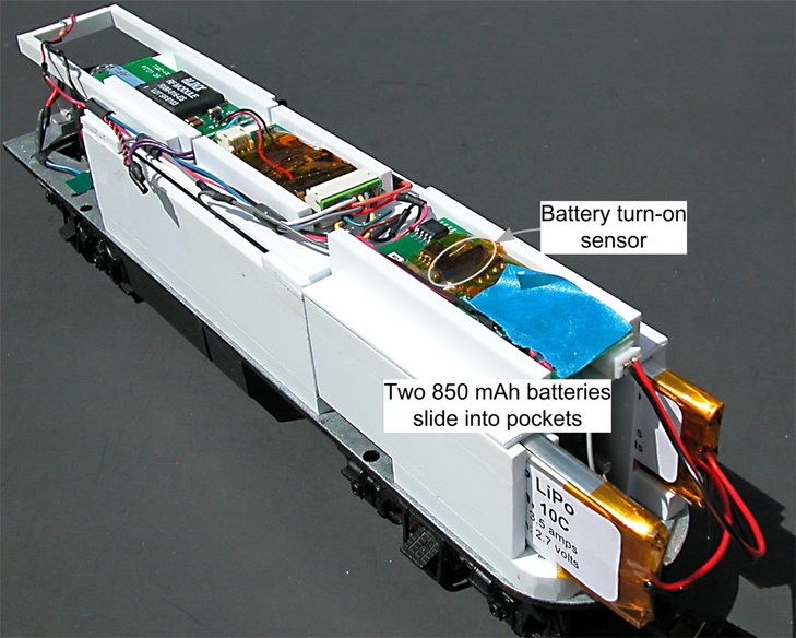
Converting this loco to S-CAB radio control and battery power supply is a relatively easy project. Since there is plenty of space, I devoted extra effort to building a framework out of styrene plastic to hold electronic components and battery. A SoundTraxx TSU-1000 sound decoder, the S-CAB radio receiver and the BPS battery power supply will sit on a shelf above the motor. Two 850 mAh batteries will be mounted on edge; one each side of the rear truck assembly.
Installation
Removing 4 screws and the front coupler allows the loco body to be removed from the chassis. The rear truck-mounted coupler does not obstruct removal of the body shell. Each truck is secured by a self locking nut, which, when removed, allows the truck to drop from it's mounting. In the photo below, I've also removed drive shafts as well as some wiring for track power pick-up and headlight. The die-cast metal frame is simple and functional, providing a good foundation for constructing some plastic framework to keep the rest of the installation tidy and secure.
The entire installation is two assemblies; battery power supply and batteries at the rear of the loco chassis; decoder, radio receiver and speaker in the middle and the loco cab is left unobstructed except for a frame (to mount a marker light) that is barely visible above the cab windows. For easy access to motor and drive shafts, the plastic framework is mounted with screws accessible from underside of the loco. The retaining nut for the rear truck can be adjusted by moving the BPS circuit board out of the way.
I forgot to remove the blue masking tape when taking the photos below, but it's something I do quite frequently to keep unruly tangles of wire under control during assembly. Paint masking tape has the advantage of being sticky enough to hold wiring out of the way and does no damage when being removed.
Since batteries don't last forever, it's best if they are accessible, as illustrated in the photo below. The BPS circuit board should be mounted so that the magnetic sensor is close to roof or side of the model where it can be activated by a magnetic wand/pencil. If the BPS board must be buried deep within the model, the sensor can be removed from the board and glued to the model's shell with wiring back to the BPS.
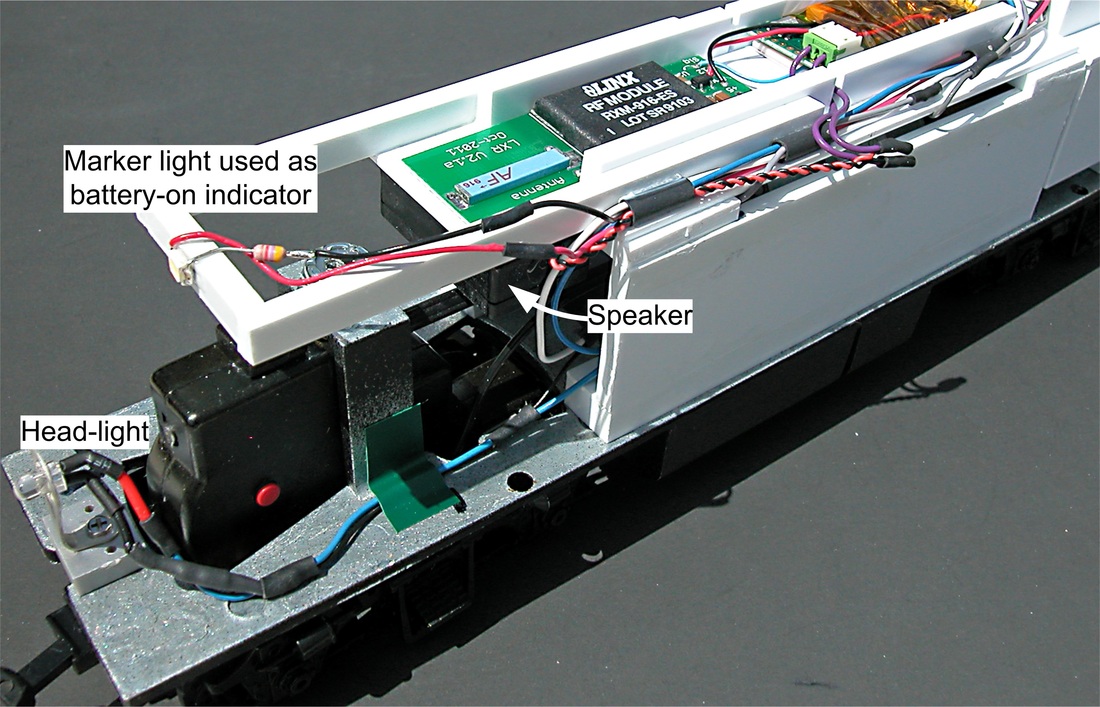
Below is a view from the front of the loco showing the factory installed headlight, which I've wired with a 4,700 ohm series resistor and connected the the decoder headlight output (white and blue leads). I've also added a small surface mount LED as a marker light (also with a 4,700 ohm resistor) and powered directly from the BPS 12 volt output. It's primary purpose is to indicate when battery power in turned on. Sound from the decoder will also confirm power is on, but not if sound has been muted.
Barely visible below the radio antenna is a model DS1425-8 speaker from RailMaster Hobbies. It's already assembled in an enclosure (16x27x9 mm) and produces very good sound for its size.
Testing and Tweaking
A neat aspect of this assembly is no components (e.g. lights) are mounted on the loco shell and therefore, there is no wiring between chassis and body of the model. All testing and initial programming of decoder CVs is done before closing up the model.
Operating Tests: Since Tsunami CV default settings are compatible with S-CAB, initial test runs are done before adjusting decoder Configuration Variables (CVs). Since I'd previously checked BPS operation, I began this running test with no track power and turned on battery power with the magnetic sensor. Using an S-CAB throttle and factory default decoder address "3", the loco moved slowly at speed step 1, direction control operated correctly, headlight control worked as expected, sound volume was good, and function output F5 turned off battery power as planned.
Battery charging: For this test, I connect a variable voltage DC power supply with current measurement to the rails and slowly increased voltage while watching current measurement. At about 5 to 6 volts, the decoder came to life and the marker light indicated track power has been detected. Current reading (typically about 200 to 400 mA) confirmed battery was charging. When DC power supply to the track was switched off, decoder and marker light continued to operate on battery power. All was good.
Decoder CVs: The basic decoder CVs can be programmed with an S-CAB throttle using broadcast mode. This requires that the "ALL" key be pressed immediately after switching the throttle to CV mode. I set CV values as follows:
CV1, decoder address, new value "6"
CV2, minimum speed, new value "1"
CV3, acceleration, new value, "20"
CV4, deceleration, new value "20"
CV5, maximum speed, no change
CV6, mid-speed, default value, "0"
CV29, decoder configuration, set to S-CAB default value "0" (The actual value stored in the decoder is "2")
Replacing the loco body: In this case, the body shell slips over the fully wired and tested chassis. Before attempting this, I used electrical insulating tape to tidy up any wiring likely to cause problems by getting stuck as the shell is maneuvered over the plastic frame holding the components. This is also the right time to make sure all wiring is properly insulated.
Once the loco body is securely in place, there is one more check to be sure the magnetic sensor is located close enough to the underside of the loco hood to reliably detect the magnetic wand. (Magnet actuation range is between 0.375 and 0.5 inches.)
Load Test: I performed this test with track power on. The idea is to prevent loco movement without applying pressure that artificially increases traction. The objective is to measure current consumption at the point where the loco loses traction and wheels begin to slip. This loco has plenty of traction; I had my hand blocking forward motion and the loco simply slide the track across my workbench. With track secured and the loco wheels slipping, current consumption was approximately 800 mA. This is right at the short-term overload capability of the BPS when operating on battery power. However, without the assist of track power, BPS current limiting would automatically lower voltage to reduce load and prevent BPS overload.


