|
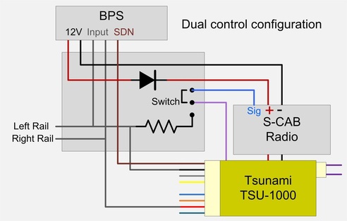
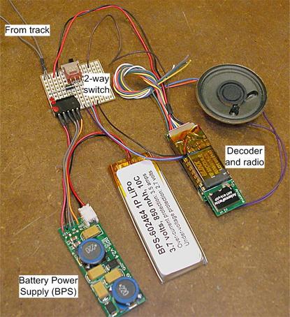
This innovation began with a customer inquiry. Richard is scratch-building an O-scale model in which he plans to install a Tsunami sound decoder. He wants to use S-CAB radio control and BPS battery power and operate the model on both his home railroad and his local club layout, which uses conventional DCC with wireless throttles. Since the club's wireless throttles operate at a radio frequency almost the same as S-CAB, radio interference prevents simultaneous use of both systems. I suggested we consider a dual control configuration to allow S-CAB battery power operation at home and use of the club's existing DCC system when operating on their layout. With this arrangement, Richard can operate with S-CAB at home, then switch to conventional DCC before taking the model to his club's layout where he can use one of their wireless throttles. Finding space for the necessary switch seems feasible in an O-scale model. The configuration I will describe provides two methods of control as well as two power sources for the model; power from the rails when DCC is present and from the battery when there is no track power. No switching is required to implement the dual power source and the transition is virtually instantaneous making the model oblivious to track power glitches and interruptions. As a bonus; the battery charges while the model runs on track power. For readers interested in how it's done, I've included a diagram. For those who prefer to skip the theory and simply decide if it's something useful, I photographed the completed setup during work-bench testing. The required components (a diode, a resistor and a switch) are all wired on a simple circuit board, which is easily assembled by hand. Engineering: It's useful to distinguish between DCC power and DCC signal. The former is supplied to the track and used to provide both power as well as communicate instructions thru DCC messages. In the decoder, track DCC is rectified to provide DC power supply and the DCC signal, with its encoded message, is separated and eventually finds its way to the decoder's microprocessor. Looking at the schematic, left and right rail inputs go to both the BPS (for battery charging) and to the decoder thru it's black and red connections (consistent with NMRA standards). These black/red connections provide power to the decoder. Notice that the left rail input also connects to a resistor and from that resistor to a 2-way switch. The purpose of the resistor is to prevent track voltage passing thru the switch and destroying the decoder's microprocessor. The blue connection to the switch is DCC signal derived from S-CAB radio. Depending on switch position, the purple wire carries a DCC signal derived from either track or radio to the decoder. The BPS feeds power to the radio and decoder thru a diode, the purpose of which is to prevent back-feed to the BPS from the decoder's rectified track power. As a result of the diode, the decoder will be powered by the higher of rectified track DCC or 12 volt BPS output. The brown connection is Tsunami function F5 output, which is used to turn off battery power when the loco is not in use. Application: Here is the system as it will be delivered to the client (with a smaller, better quality speaker) photographed while on the work-bench for testing. The decoder and radio is standard S-CAB conversion of a TSU-1000 decoder with one wire added to bring the DCC signal from the radio (blue wire) thru the switch and back to the decoder (purple wire). As viewed in the photo, switch left connects track DCC to the decoder; switch right connects radio DCC. The BPS and battery are also standard S-CAB products. The perforated prototyping board is customized for this application. (A factory-made PCB could be much smaller.) Gray wires from rail pick-up are connected thru the circuit board to both BPS (gray wires) and the right/left rail (red/black) connections of the decoder's 9-pin JST socket. 12 volt supply from the BPS connects directly to the decoder thru a diode mounted on the circuit board. The battery has sufficient energy storage to serve as both primary (on home layout) and back-up power source (at the club). Bench testing demonstrates that the configuration works exactly as expected. I hope, in a future blog post, to follow-up with a report of the client's experience, both at home and on his club's layout. Acknowledgement Tsunami decoders are a SoundTraxx product. The manufacturer's proprietary rights are acknowledged. Decoder modifications described herein are not endorsed or recommended by SoundTraxx and modifying a decoder voids manufacturer's warranty. However, I never deliver anything without thorough testing.
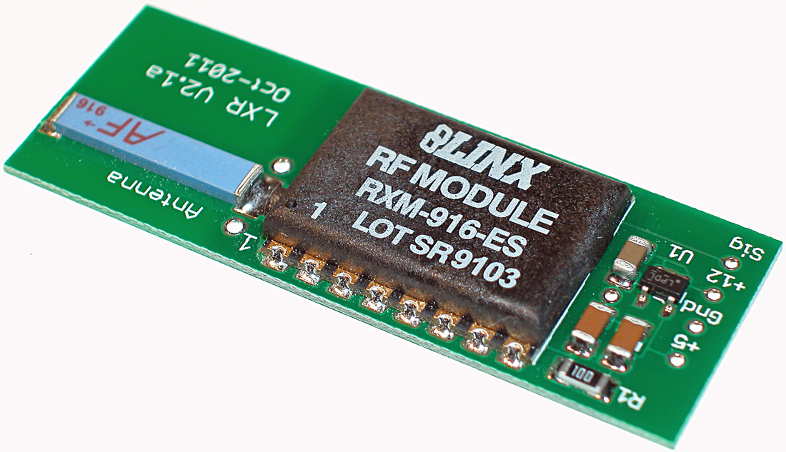
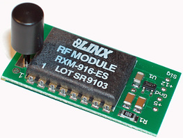
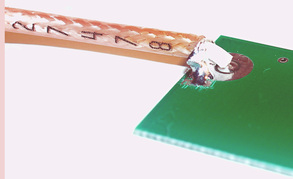
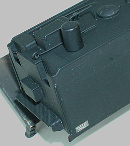
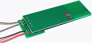
I'll discuss two topics in this blog: radio antenna options and use of a DCC adapter. Antenna OptionsThe S-CAB radio receiver is designed to be bundled with selected decoders to create a ready-to-install package following exactly the same installation instructions as a non-radio decoder of the same brand. How the antenna is mounted on the radio receiver circuit board affects radio reception, but loco installation space limitations sometimes require a less-than-ideal antenna mounting. These photos show three options using what is called a "chip" antenna. Antenna orientation affects radio reception and reliable transmission distance deceases as the antenna becomes less effective. Informal tests using an S-CAB Throttle indicate reliable transmission distance of 30 to 50 feet with lengthwise and vertical antennas. Crosswise mounting produces the smallest package, but radio range is reduced to 15 feet. These tests were performed indoors where walls, metal ducting, electrical wiring, etc. interfere with radio propagation. Outdoor transmission distances can be 100 feet or more.  Planar antenna Planar antenna The planar antenna to the right, which looks like a tiny circuit board, performs well and is definitely superior to the cross-wise mounted chip antenna. It keeps the radio receiver assembly no thicker than what is required for the radio module (5/32") and overall length is 1.75" compared to 2" for the lengthwise chip antenna. Precautions are required when locating radios inside metal enclosures, such as a brass loco tender or diesel loco metal body. S-CAB allows a number of antenna options to deal with this issue. For steam locos, the tender coal load is a convenient place to hide the antenna and vertical mounting of the chip antenna gives best reception.
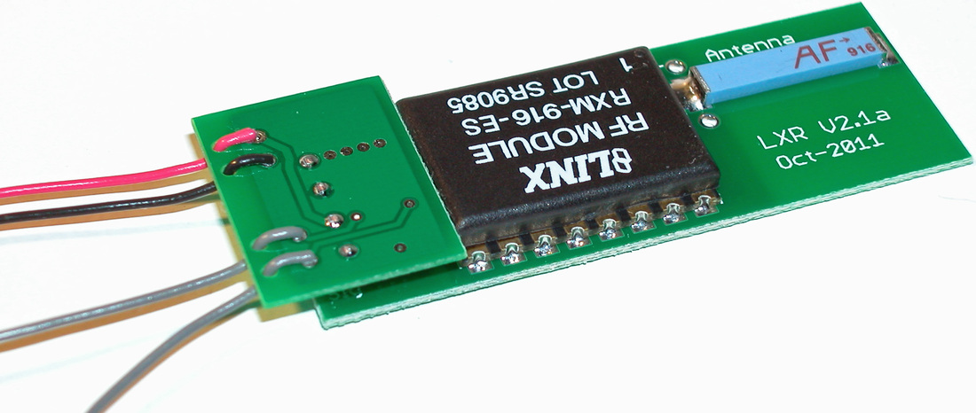
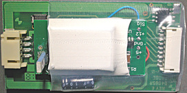
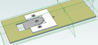
However, a 3 inch length of wire makes a reasonable antenna, but it's difficult to prevent it tangling with other wires or laying against a metal surface when reassembling a loco. Use single stand wire, thick enough (20 to 24 AWG) so it's not too flexible and keep it insulated from any metal surfaces. DCC AdapterFor modelers with obsolete or rarely used decoders, S-CAB radio receivers can be equipped with a "DCC adapter" which provides a DCC output identical to track DCC pick-up. When this output is connected to a decoder (instead of rail pick-up), the decoder is not aware that commands are communicated by radio instead of thru the track. These photos show the DCC adapter mounted on the radio receiver. The grey wires connect to the right/left rail inputs of a decoder (polarity is not important). The adapter's red and black leads are positive and negative battery power connections. Adapter and radio receiver can be separated, but four connecting wires are required. The disadvantage of this arrangement is full power for the decoder must be provided by the adapter instead of connecting battery power directly to the decoder. DCC output from the adapter is limited to 1 amp maximum, which is adequate for most smaller scale locos. Here is a report I received from Peter Vanvliet. His latest run time from a 2 AH battery in an S-scale loco is remarkable and demonstrates the benefit of a good motor and mechanism. Earlier this year I installed the S-CAB system with double-battery into my S-scale American Models FA-2 engine. It was very hard to control the speed. I subsequently had Dave at NWSL install a new motor in the frame. He used a "20x32" motor. I converted the loco back to S-CAB. I then fully charged the battery and over the past two days I have given the engine my endurance test. I ran it back and forth my layout, about 20 feet each direction. I just kept flipping the throttle's direction button at the end of the line. I had momentum set up in the decoder. Over the past two days it has run for a combined total of six hours and 15 minutes. I have grown tired of having to watch the engine and flipping the throttle, so I am stopping here, but I would imagine it can keep going for a while longer. My layout has no track power on it at all. So, for my three engines, to sum up, running light on unpowered track, I have these results: 950mAh = 1.5 hours (NWSL motor) 1000mAh = 3 hours (S-Helper Service unbranded motor) 2000mAh = 6.25+ hours (NWSL motor) Steam loco tenders provide convenient space for batteries and decoders. However, wiring between tender and engine can easily become an untidy tangle making it difficult to separate engine and tender and sometimes restricting free movement of the tender's leading truck. A client (Bill) and I have jointly undertaken S-CAB conversion of a brass loco; he is re-motoring the loco and I'm responsible for installing a complete S-CAB system in the tender. We needed a connector between tender and loco and Bill suggested I look at SoundTraxx DBX-9000 wiring kit. 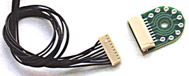 It provides a 9-pin socket and a compatible cable harness with wires that are thin, flexible and black. Nine wires is more than we need, but the unused wires are easily removed from the plug. Bill's project required only 5 wires; 2 for motor, 2 for headlight and 1 for right-rail pickup. I assigned pins in conformance with NMRA specs for a 9-pin JST socket. The center mounting hole fits a 2/56 screw. For installation, the first idea is to mount the DBX circuit board on the underside of the tender chassis. The flaws in this simple plan were soon apparent. The tender chassis (floor) is solid brass sheet, so we need insulation. We also have to cut a hole to route wires from inside to the underside of the tender. However, the show-stopper was insufficient clearance to accommodate the DBX between top of the tender's leading truck frame and the tender floor above. A Better Plan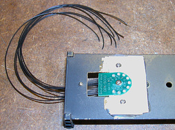 Mounting the DBX on top side of the tender floor is more complicated but has several advantages. Not only can the engine be unplugged from the tender, but the DBX, with wires attached, can be separated from the chassis, making it much easier to access most of the S-CAB components, which are mounted in the body of the tender. The speaker is the only item directly attached to the tender chassis. This installation required a rectangular opening in the tender floor, which I admit was tedious work. The DBX is mounted on a piece of styrene sheet which provides insulation from chassis and allows the DBX to be tilted downwards to unplug the engine cable harness. Here are top and bottom views from a 3D CAD design. If you have an up-to-date version of Adobe try this link to view a 3D file.
To prevent a loco's battery slowly discharging when not in use, BPS includes an electronic switch to isolate the battery from all external components. I'll attempt to answer several questions related to how battery on/off is actuated. Turn On If a loco has rail pick-up connections, BPS turns on whenever track voltage is detected. If the loco has no rail pick-up or track is not powered, a magnetic sensor mounted on the BPS circuit board is actuated with a magnetic wand. This requires the sensor to be mounted where it's convenient to bring the wand within actuation distance (about 1/2 inch). Where it's not convenient to mount the BPS close to roof or side of a loco, a sensor can be separated from the circuit board and glued directly to a suitable non-magnetic surface using appropriate adhesive or epoxy. Turn Off BPS is designed to be turned off using a decoder function command, but differences in decoder behavior created so much confusion early in the life of BPS that a push-button is included as the default method of turn-off. The following discussion deals with turn-off procedures, but first, a few more remarks regarding the default push-button switch. Any momentary contact connecting (shorting) the orange colored wires is all that's required. A magnetic sensor (same component as used for turn-on) will work. Another point to remember: Any charging input (from track pick-up or a charging socket) overrides turn-off. Neither push-button nor decoder function command will turn off battery power when charging input is present. Turn-off using a decoder function command Decoder function outputs control devices (lights, for example) by "grounding" the appropriate output. For example, a loco's headlight is connected to a decoder's white and blue wires where blue is positive common and white is the function output intended for headlight control. A decoder turns headlight on by connecting its white lead (thru a transistor) to ground.  Looking at the BPS, one of the orange leads is a ground connection; the other (call it the shutdown lead) performs turn-off. If a decoder function output is connected to the shutdown lead, a function 'on' command will ground it and turn off the battery, assuming there is no input charging power. When the battery turns off, everything shuts down, including the decoder, which is exactly what we want. So where's the confusion? When turned off, some decoders (NCE, for example) "remember" the state of their function outputs; others (SoundTraxx Tsunami, for example) forget function outputs and there is no confusion in this case. Shutdown using a Tsunami decoder is documented elsewhere. Confusion occurs when attempting to turn on a BPS that was turned off by a function command from a decoder that remembers its state during shutdown. Suppose the loco has no track power and the magnetic wand is used to turn battery on. As soon as the decoder starts, it turns on its remembered function output, which turns off the battery and everything shuts down. A user perceives this behavior as a BPS problem. What happens if the loco has track power? In this case, track power overrides the decoder's function output and turn-on appears normal. However, the decoder will turn off battery power as soon as charging input is removed. To the user, everything is normal until the loco moves onto unpowered track and stops. Again, it looks like a BPS problem. A turn-on procedure that always works This procedure works because track power (charging input) overrides any attempt to turn off the battery. As soon as the decoder turns on, send a function command to turn off the remembered function output. That's it; no confusion, problem solved. However, the situation without track power requires holding the magnetic sensor on (using the magnet wand in one hand) while using the throttle (in the other hand) to send a function-off command. Definitely not convenient. Example
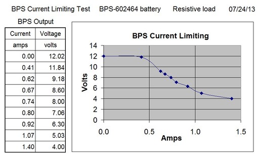
Here's an example based on a question from a modeler wanting to charge batteries while locos are idle in an engine shed or roundhouse where the building prevents manual access to turn battery on or off. A similar situation occurs with inaccessible storage sidings. For this example, the decoder is one that remembers its function outputs during shut down. Since the most convenient time to charge batteries is at the end of an operating session, the loco, having completed its tasks, enters the engine-shed where rails are powered and power is on for battery charging. A decoder battery-off command is then sent to the loco and is executed by the decoder, but charging input keeps battery power on. After several hours of charging, loco-shed rail power is turned off and the decoder, with function output on from its previous command, immediately turns off battery power. This procedure reduces risk of forgetting to turn off the battery and later discovering a flat battery. When commencing a new operating session, first turn on engine-shed track power, then transmit the appropriate battery-on (function-off) command and begin operation. The S-CAB battery power supply (BPS) provides 12 volt on-board power from a 3.7 volt lithium polymer (LiPo) battery. The design emphasizes safety; for battery, BPS components and the loco in which BPS is installed. The battery charger built into the BPS ensures the battery cannot be over-charged. A protective circuit module (PCM) integrated into the battery assembly protects the battery from over-current and under-voltage conditions. In addition, BPS output includes current limiting to prevent over-load conditions from damaging BPS components. BPS specifications define a maximum current output of 500 mA, which is adequate for HO, On3, On30 and some S scale locomotives, so long as they are in reasonably good mechanical condition. Designing for higher output would have required a larger circuit board and excluded BPS from many HO applications due to space limitations. So the trade-off between current output and size is a compromise. Based on operational experience and improved characteristics of both battery and PCM, BPS overload behavior is safe and predictable, as demonstrated in the following graph. Output voltage is constant 12 volts for current output up to 400 mA and drops to about 11 volts at 500 mA. Beyond 500 mA, output voltage drops significantly due to current limiting built into BPS. This test used a resistor as the load. A loco motor behaves differently. As voltage drops, the motor just won't produce enough power to move the loco. Conclusion: I hope this explains why I want to know the loco motor's full load current when supplying a BPS. It's also the reason BPS installation instructions require a bench test of the BPS before installing in a loco. If a loco runs well on the bench with no load, but does not run when loaded, it may be exceeding the BPS 500 mA rating. In this case, it's the loco mechanism that needs to be examined. Engineering comment: Using a resistive load extends the current range of the test to 1.4 amps. This required a
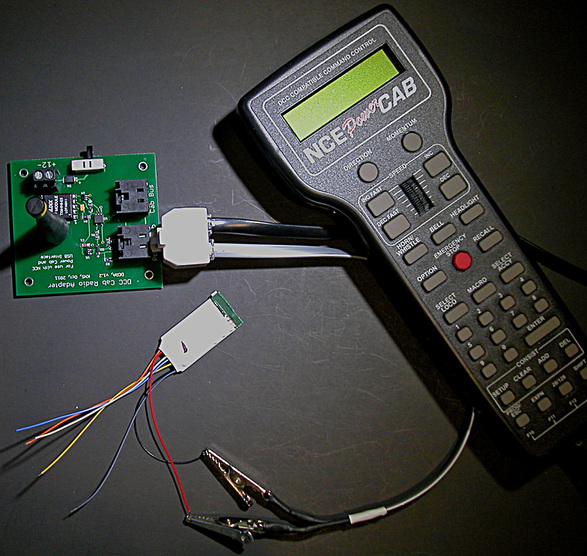
resistor of less than 3 ohms. As voltage drops, a motor will slow and ultimately stall. With current limiting, the higher the stall current, the lower the voltage. Leaving a loco decoder on full throttle with the loco stalled may be hard on the decoder and/or the motor, but the voltage will be low enough to prevent serious damage. The resistance of a HO scale loco motor is somewhat greater than 3 ohms, which means the stall current will be less than 1.4 amps. Most decoders can survive this condition. With radio control, programming decoder CVs has been concern. I've previously explained that RAPA (the Radio Programming Adapter) can be used to write CVs by radio. The question is this: Can we use RAPA to read CV values? The answer is yes, by using the setup illustrated in the following photo. The green circuit board is RAPA and a 6-wire, 2-way splitter is plugged into RAPA's PowerCab socket. RAPA also requires a 12 volt DC power supply. The small shrink-wrapped object in center of photo is an S-CAB radio-ready decoder. The splitter allows PowerCab to communicate radio commands via RAPA and at the same time connect to the decoder through its red/black wires (the right and left rail inputs in conventional thru-the-track DCC). To perform CV programming, a motor must be connected to decoder orange/gray wires. When RAPA power is turned on, PowerCAB boots up and begins DCC output. It's best to send a few speed commands to be sure radio communication is good and the motor responds correctly. Now press PowerCab's 'PROG' button repeatedly until 'Programming Track' is displayed. Press 'ENTER', then '2' to select a CV number. Enter a number, press 'ENTER' and, after a brief pause, PowerCab will display the selected CV's value. At this point, either press 'ENTER' to escape or enter a desired value followed by 'ENTER' to change the CV value. This brief explanation is certainly not an adequate set of instructions for reading/writing CV values. I just want to make it clear that S-CAB radio-ready decoders and RAPA now offer the same CV programming features as are available using a DCC programming track. We can read CVs just as easily as writing them.
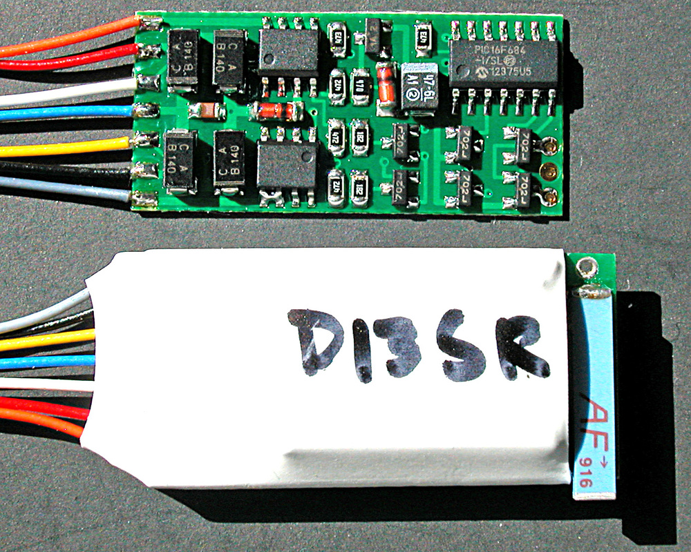
Here's a photo of an NCE D13SR decoder before and after addition of the S-CAB radio receiver. By placing the antenna cross-wise we get a smaller package. With receiver and decoder mounted back-to-back, the result is thicker (0.32"), but length (1.5") and width (0.75") are not much bigger than the decoder. Mounting the antenna in this manner is not recommended by the radio manufacturer. However, tests show good radio reception (at least 20 foot range), which is adequate for loco control. In future, this configuration will be available with no change in list price. I plan to test this same antenna arrangement with Tsunami TSU-1000 and TSU-750 sound decoders. Because of its small size and simpler wiring, the 750 is a particularly good candidate for a minimum sized sound package.
|
AuthorI'm a retired electrical engineer, but still spending more time on engineering than on my layout. These days, it's mostly about applying radio control and battery power on smaller scale layouts (HO, On3, On30) Categories
All
The photo above is not my layout. It's a great view of Seattle's King Street station by Ross Fotheringham.
Archives
December 2022
|
